Improving CNC part precision involves optimizing machine calibration, refining cutting parameters, enhancing fixturing rigidity, controlling material stability, and implementing strict inspection. Key steps include using high-precision CNC systems with thermal compensation, minimizing tool deflection, stabilizing material temperatures, and adopting in-process metrology to ensure tolerances as tight as ±0.001mm.
Detailed Analysis of Enhancing CNC Part Precision
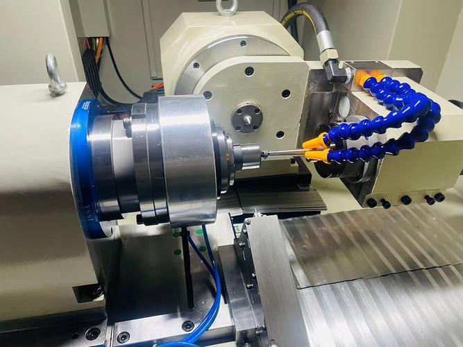
1. Machine Tool Calibration & Technical Upgrades
The foundation of precision lies in the CNC machine’s ability to maintain accurate movements, requiring advanced calibration and hardware:
- High-Precision CNC Systems: Invest in machines with 5-axis capabilities and closed-loop feedback (linear scales with ±0.0001mm resolution). For example, a DMG Mori NHX 4000 with glass scales achieves positioning accuracy of ±0.0005mm, critical for aerospace parts like turbine blades (tolerance ±0.002mm).
- Thermal Error Compensation: Machines expand/contract with temperature fluctuations (steel beds: ~0.012mm/m per °C). Integrate thermal sensors to monitor ambient and spindle temperatures, then use the controller’s software to offset axes. This reduces errors by 40–60% in long-running jobs (e.g., 8-hour machining of a 2m aluminum frame).
- Spindle & Axis Rigidity: Upgrade to spindles with ceramic bearings (runout <0.001mm) and preloaded ball screws (backlash <0.001mm). For high-speed machining (30,000 RPM), dynamic balancing minimizes vibration, ensuring consistent cuts in titanium alloys (Ti-6Al-4V).
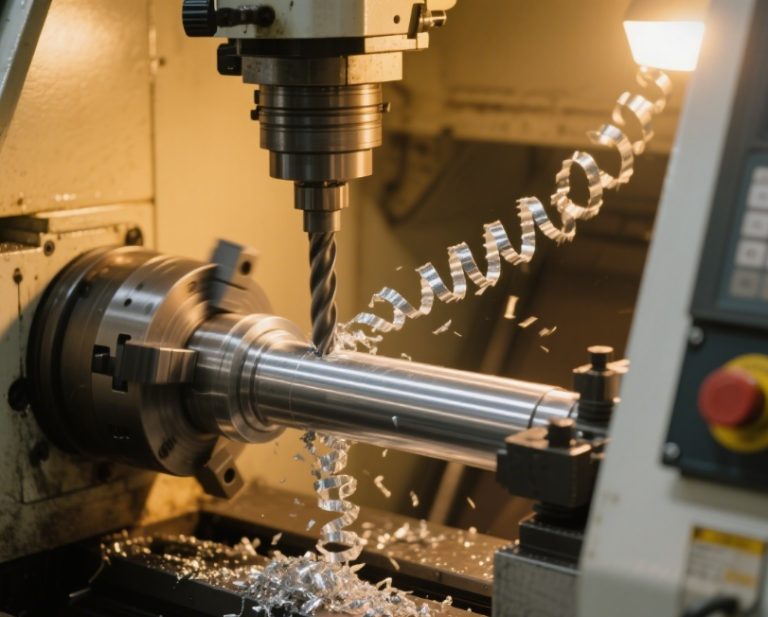
2. Tooling Optimization & Cutting Parameters
Tool selection and cutting conditions directly impact dimensional accuracy by reducing deflection and wear:
- Low-Deflection Tooling: Use short, rigid tools (overhang ≤3× diameter) to minimize bending. A 10mm carbide end mill with a 20mm overhang deflects 50% less than one with 40mm overhang, critical for tight slots (±0.005mm) in mold cavities. Coatings like TiAlN or AlCrN extend tool life by 2–3x, maintaining precision across 500+ parts.
- High-Speed, Low-Force Cutting: For thin-walled parts (0.5–2mm), use spindle speeds of 15,000–40,000 RPM and feed rates of 0.05–0.1 mm/rev. This reduces cutting forces by 30–50%, preventing deformation in aluminum brackets (tolerance ±0.01mm). For hard materials (Inconel 718), carbide tools with negative rake angles (5–10°) shear material cleanly, avoiding work hardening.
- Adaptive Machining: Use CAM software with AI-driven toolpaths (e.g., Mastercam’s Dynamic Motion) that adjust feeds/speeds in real time based on material density. This compensates for forging inconsistencies in steel blanks, ensuring ±0.003mm tolerance in automotive crankshafts.
3. Material Stability & Temperature Control
Material properties and thermal expansion are major sources of error, requiring strict controls:
- Stress Relief & Homogeneity: Prior to machining, anneal metals (e.g., 6061 aluminum at 350°C for 2 hours) to release residual stresses from rolling/forging. This reduces post-machining warpage by 70% in large parts (e.g., 1m-long structural beams). For plastics (ABS), use dried pellets (moisture <0.02%) to prevent dimensional changes during machining.
- Temperature Stabilization: Acclimate materials to the workshop (20±1°C) for 24–48 hours. A 5°C 温差 (temperature difference) in a 100mm steel part causes 0.006mm expansion—avoided by storing blanks in climate-controlled rooms. During machining, use coolant at 20±2°C to prevent heat-induced growth in aluminum (expansion rate: 23×10⁻⁶/°C).
4. Fixturing & Workholding Design
Rigid fixturing prevents workpiece movement, a common cause of dimensional errors:
- Custom Jigs & Vacuum Chucks: For irregular shapes (e.g., aerospace brackets), 3D-printed fixtures with locator pins (±0.002mm) ensure repeatable positioning. Vacuum chucks with porous ceramic surfaces provide uniform clamping for thin sheets (0.3mm stainless steel), reducing distortion by 50% vs. mechanical clamps.
- Low-Deformation Clamping: Distribute clamping force using multi-point vises (4–6 jaws) instead of 2-jaw designs. For a 150mm aluminum plate, 4-point clamping reduces deflection from 0.02mm to <0.005mm, critical for flatness (±0.003mm) in optical instrument bases.
5. Process Controls & In-Process Inspection
Real-time measurement and process monitoring catch errors before they accumulate:
- In-Process Metrology: Integrate Renishaw OMP40 probes into CNC machines to measure critical features (e.g., hole diameter, slot width) after roughing. For example, if a bore is 0.003mm undersized, the controller adjusts the finishing pass to correct it, ensuring final tolerance ±0.001mm.
- Statistical Process Control (SPC): For batch production, track dimensions (e.g., shaft diameter) across 50+ parts using control charts. If measurements drift (e.g., +0.001mm per 100 parts), replace tools or adjust offsets, maintaining consistency in automotive sensors (tolerance ±0.005mm).
- Post-Machining Verification: Use high-precision CMMs (accuracy ±0.0005mm) or optical scanners (resolution 0.001mm) to validate GD&T features (flatness, perpendicularity). For free-form surfaces (e.g., turbine blades), 3D scanning compares the part to CAD, ensuring aerodynamic profiles (±0.003mm).
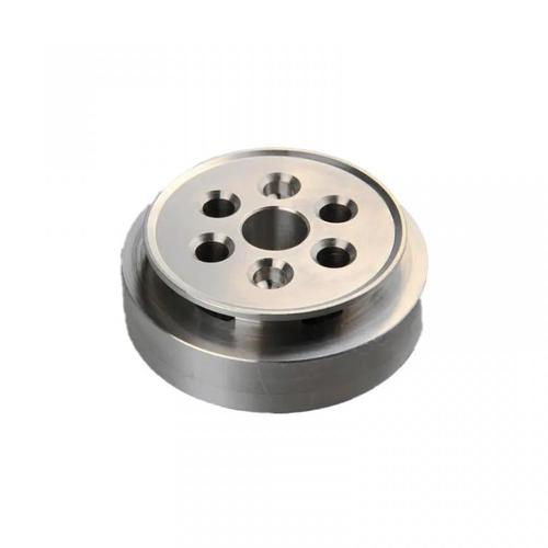
6. Part Design & Geometry Considerations
Design choices influence achievable precision, requiring collaboration between engineers and machinists:
- Avoid Sharp Corners & Deep Slots: Use radii ≥0.1mm to reduce tool deflection and scallop height (step between tool paths). A slot with a 0.5mm radius machines 30% more accurately than a sharp corner, as the tool maintains better contact.
- Thin-Wall Reinforcement: Add ribs or gussets to 0.5–1mm walls to prevent vibration-induced chatter. For example, a 100mm-long aluminum bracket with 1mm walls gains 50% rigidity with 2mm ribs, ensuring ±0.01mm flatness.
- Datum Consistency: Design parts with clear, accessible datums (e.g., a flat face or precision hole) to simplify fixturing. This reduces setup errors by 40% in complex assemblies (e.g., medical device housings with multiple holes).
7. Industry-Specific Precision Requirements
Different sectors demand tailored approaches to meet extreme tolerances:
- Aerospace: Engine fuel injectors (titanium) require ±0.001mm hole positioning to ensure fuel atomization. Machining uses 5-axis machines with laser calibration (monthly) and in-process probing after every 10 parts.
- Medical Devices: Surgical implants (cobalt-chrome) need ±0.002mm tolerance for bone fit. Processes include EDM (electrical discharge machining) for micro-features and CMM inspection under 50x magnification.
- Electronics: Semiconductor test sockets (brass) require pin positions within ±0.005mm to align with chip contacts. Machining uses micro-CNCs (spindle speed 100,000 RPM) and diamond tools for ultra-precise cuts.
- Optics: Lens mounts (aluminum) demand flatness <0.001mm to prevent image distortion. Machining in a temperature-controlled cleanroom (20±0.1°C) and post-processing with lapping achieves Ra <0.02μm surfaces.
8. Challenges & Mitigation Strategies
- Thermal Distortion: Large parts (e.g., 3m steel plates) warp during machining due to uneven cooling. Use coolant at 18°C, and machine in segments with re-clamping to distribute heat.
- Tool Wear: Progressive wear (0.001mm/hour) in Inconel machining shifts dimensions. Use tool life management software to trigger replacements at 80% wear, ensuring parts stay within ±0.003mm.
- Material Inconsistencies: Forged blanks with 3–5% thickness variation cause errors. Adaptive machining (sensor-based toolpath adjustment) compensates for these variations, maintaining precision in automotive 连杆 (connecting rods).
By integrating machine calibration, tooling optimization, material control, and rigorous inspection, CNC parts can achieve tolerances as tight as ±0.001mm, meeting the demands of aerospace, medical, and other high-precision industries.