Chatter marks on CNC parts, caused by vibration between tool, workpiece, or machine, can be fixed by optimizing cutting parameters (avoiding resonance), enhancing rigidity (shorter tool overhang, rigid fixtures), using damping technologies, and refining tool paths. These steps reduce vibration amplitude, ensuring smooth surfaces across materials like metals and composites.
Detailed Analysis of Eliminating Chatter Marks in CNC Machining
1. Technical Causes & Vibration Control Technologies
Chatter arises from resonant vibrations (natural frequency matching cutting forces), requiring targeted technical fixes:
-
Machine Tool Rigidity Enhancement:
- Structural Stiffness: Check for loose components (e.g., ball screw nuts, guideway bolts) and tighten to eliminate backlash (target <0.001mm). Reinforce machine bases with vibration-damping materials (e.g., polymer concrete) to reduce frame resonance—critical for large machines (e.g., 5-axis mills for aerospace parts), where base flexing amplifies chatter.
- Spindle Stability: Use high-rigidity spindles (e.g., 30,000 RPM with ceramic bearings) to minimize runout (<0.002mm). For older machines, retrofitting with spindle balancing kits reduces vibration by 40%, especially during high-speed milling of aluminum.
-
Tooling & Damping Solutions:
- Minimize Tool Overhang: Tool overhang >3× tool diameter increases vibration. For a 10mm end mill, limit overhang to <30mm; use shorter tools or extended shanks for deep features. This reduces deflection by 50% in steel machining, eliminating chatter marks on mold cavities.
- Damping Technologies: Attach dynamic dampers (e.g., OTT-Jakob) to tool holders to absorb vibration energy. For thin-walled parts (e.g., 0.8mm titanium brackets), dampers reduce chatter amplitude from 0.1mm to <0.01mm, achieving Ra 0.8μm surfaces.
- Adaptive Toolpaths: CAM software with “chatter avoidance” algorithms (e.g., Mastercam Dynamic Motion) adjusts feed rates in real time to skip resonant frequencies, reducing marks on curved surfaces (e.g., turbine blades).
2. Cutting Parameter Optimization
Resonance between cutting forces and system natural frequencies causes chatter, requiring precise parameter tuning:
-
Spindle Speed Adjustment: Identify and avoid resonance frequencies (measured via vibration sensors). For example, a 10mm carbide end mill in aluminum may resonate at 8,000 RPM—shifting to 10,000 RPM or 6,000 RPM eliminates chatter. Use “spindle speed maps” (created via trial cuts) to mark safe ranges for each tool/material pair.
-
Feed Rate & Depth Control:
- Increased Feed Rates: Higher feeds (0.1–0.2 mm/rev) for roughing reduce time in resonant zones, though finish passes need lower feeds (0.05–0.1 mm/rev) to smooth surfaces. For steel, a 0.15 mm/rev feed during roughing cuts chatter by 30% vs. 0.08 mm/rev.
- Reduced Cutting Depth: Finish cuts with 0.1–0.3mm depth minimize forces, critical for thin walls. A 0.2mm depth on a 1mm-thick brass part avoids flexing, unlike 0.5mm depth which induces vibration.
-
Coolant & Lubrication: High-pressure coolant (70–100 bar) reduces friction, lowering cutting forces by 15–20%. For titanium, oil-based coolants (vs. water-soluble) enhance lubricity, reducing chatter in deep holes (e.g., 20mm-deep in medical implants).
3. Material & Workpiece Factors
Material properties and workpiece geometry influence vibration, demanding tailored solutions:
-
Material Stiffness & Damping:
- Metals: Titanium (Ti-6Al-4V) has low damping, amplifying chatter—use carbide tools with AlCrN coatings and high speeds (15,000 RPM) to minimize contact time. Steel (4140) with higher damping responds better to moderate speeds (8,000–12,000 RPM).
- Composites: CFRP’s uneven stiffness (fibers vs. resin) causes erratic vibration. Use PCD tools with negative rake angles (5–10°) and low feeds (0.01–0.03 mm/rev) to shear fibers cleanly, reducing chatter-induced delamination.
-
Workpiece Geometry Fixes:
- Thin-Walled Parts: Add temporary supports (e.g., 3D-printed jigs, foam backers) to stiffen 0.5–2mm walls. For example, a 100mm-long aluminum bracket with 1mm walls gains 50% rigidity with internal foam supports, eliminating lateral vibration.
- Large/Irregular Parts: Segment machining into smaller sections to reduce unsupported lengths. A 2m steel beam machined in 500mm segments (with re-clamping) vibrates 70% less than machining in one pass.
4. Fixturing & Workholding Improvements
Inadequate clamping allows workpiece movement, amplifying chatter—solutions focus on rigidity and damping:
-
Rigid Fixturing Design:
- Multi-Point Clamping: Distribute force across large surfaces (e.g., 4 clamps for a 300×300mm plate) instead of 2 clamps, reducing deflection by 40%. Use machined locating pins (±0.002mm) to prevent shifting during cuts.
- Low-Profile Clamps: Minimize clamp height to reduce lever-arm effects. For example, 20mm-tall clamps on a 50mm-thick part reduce vibration vs. 50mm-tall clamps, which act as cantilevers.
-
Damping Workholders: Line fixtures with viscoelastic materials (e.g., Sorbothane) to absorb vibration. For precision grinding of bearing races, these materials reduce resonant amplitude by 60%, achieving Ra 0.05μm surfaces.
-
Vacuum & Magnetic Chucks: For thin sheets (e.g., 0.3mm stainless steel), vacuum chucks provide uniform holding without distortion. Magnetic chucks (for ferrous parts) with fine-pole spacing (1mm) enhance grip, reducing chatter in high-speed milling.
5. Industry-Specific Solutions
Different sectors face unique chatter challenges, requiring specialized approaches:
-
Aerospace & Defense: Critical parts (e.g., engine mounts) demand chatter-free surfaces to avoid stress concentration. Use 5-axis machines with adaptive control (e.g., Siemens Sinumerik One) that adjusts feeds/speeds based on real-time vibration data. Post-machining, laser profilometers verify no chatter marks (≤0.001mm depth).
-
Automotive Mass Production: High-volume parts (e.g., aluminum wheel hubs) use dedicated machining cells with rigid tooling and fixed parameters (e.g., 12,000 RPM, 0.15 mm/rev feed) proven to avoid resonance. Robotic loaders ensure consistent fixturing, reducing batch-to-batch variation.
-
Medical Devices: Implants (e.g., hip stems) require smooth surfaces to prevent tissue irritation. Machining uses low-vibration spindles (20,000 RPM) and diamond tools, with post-process inspection under 100x magnification to detect sub-micron chatter marks.
-
Precision Tooling: Mold inserts (steel) for optical lenses must be chatter-free (Ra <0.02μm). Use ultra-precision CNCs (e.g., Moore Nanotech) with air bearings to eliminate mechanical vibration, paired with slow, steady feeds (0.01 mm/rev).
6. Troubleshooting Common Chatter Scenarios
-
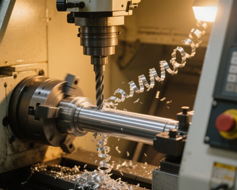
Milling Flat Surfaces: Chatter appears as wavy patterns (1–5mm spacing). Fix by shortening tool overhang (e.g., from 40mm to 20mm), increasing feed rate (0.1→0.15 mm/rev), or adding a dynamic damper to the spindle.
-
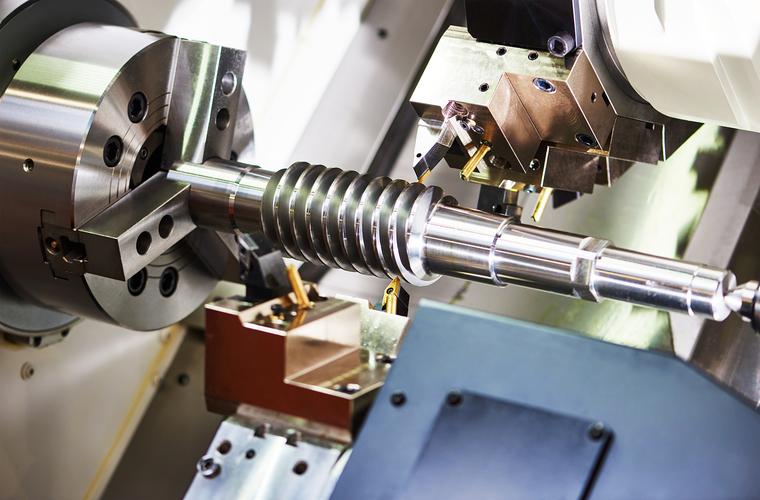
Turning Cylindrical Parts: Axial chatter marks (parallel to axis) stem from loose tailstocks. Tighten tailstock pressure, use a follow rest for long shafts (L/D >5), or reduce cutting depth (0.5→0.3mm).
-
Deep Cavity Machining: Radial chatter in slots (depth >10× diameter) is fixed by step-down cuts (2mm per pass instead of 5mm), using coolant through the tool to flush chips, and selecting short-length end mills with 4 flutes for rigidity.
By integrating machine rigidity enhancements, parameter tuning, material-specific strategies, and industry-tailored solutions, CNC machined parts can achieve consistent, chatter-free surfaces—ensuring both functional performance and aesthetic quality.