Simple and Practical Tips for Successful Plastic Part Design
1. Wall Thickness Design
Wall thickness is one of the most important design considerations.
Keep it uniform
- All parts of your design should have similar thickness
- This prevents problems like warping and sink marks
Avoid extremes
- Too thin: Material can’t flow properly
- Too thick: Causes long cooling times and defects
Recommended thickness range
- Most plastics: 0.04 to 0.15 inches (1 to 3.8 mm)
- Check specific material recommendations
2. Draft Angles
Draft angles help parts release from the mold easily.
What is draft?
- A slight taper on vertical surfaces
- Like a cone shape instead of a cylinder
How much draft do you need?
- Minimum: 1 degree per inch of depth
- Textured surfaces: 2-3 degrees
- Deep cavities: More draft is better
Why it’s important
- Prevents parts from sticking in the mold
- Reduces damage to parts during ejection
- Extends mold life
3. Corner Radii
Sharp corners cause problems in injection molding.
Replace sharp corners with radii
- Internal corners: Radius = 0.5 × wall thickness
- External corners: Radius = 1.5 × wall thickness
Benefits of radii
- Improves material flow
- Reduces stress concentrations
- Prevents cracks and breakage
- Makes parts stronger
What happens with sharp corners?
- Material can’t flow smoothly
- Creates weak points in the part
- Causes stress risers
4. Rib Design
Ribs add strength without increasing wall thickness.
Proper rib dimensions
- Rib thickness = 0.6 × wall thickness
- Rib height = 3-4 × wall thickness
- Space between ribs = 2 × wall thickness
Design tips
- Add fillets at rib bases
- Taper rib sides for easier ejection
- Avoid thick sections at rib intersections
Advantages
- Increases stiffness and strength
- Reduces material usage
- Shortens cooling time
- Prevents sink marks
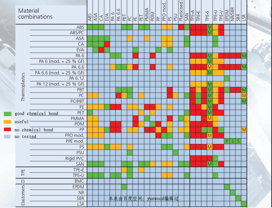
5. Material Selection
Choosing the right material is crucial.
Common materials
- ABS: Strong, impact resistant, good for housings
- Polypropylene: Flexible, chemical resistant, low cost
- Polycarbonate: Transparent, high impact strength
- Nylon: Tough, wear resistant, good for gears
- Acrylic: Clear, scratch resistant, good optics
Selection factors
- Strength requirements
- Temperature resistance
- Chemical exposure
- Appearance needs
- Cost considerations
6. Shrinkage Considerations
All plastics shrink when cooled.
Understanding shrinkage
- Different materials shrink different amounts
- Typical range: 0.5% to 2.5%
- Semi-crystalline plastics shrink more than amorphous
Design compensation
- Scale your design larger to account for shrinkage
- Consult material data sheets for specific values
- Consider directional shrinkage effects
Avoiding problems
- Uniform wall thickness reduces uneven shrinkage
- Proper cooling minimizes warping
- Adequate draft helps with shrinkage issues

7. Gate Design
Gates control how material enters the mold.
Common gate types
- Edge gate: Simple, economical, good for most parts
- Pin gate: Small, leaves minimal 痕迹,good for cosmetics
- Submarine gate: Hidden, automatic trimming
- Hot runner gate: For high volume production
Gate placement
- Position at thickest section
- Avoid flowing against cores
- Minimize flow distance
- Consider cosmetic requirements
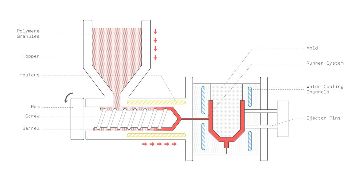
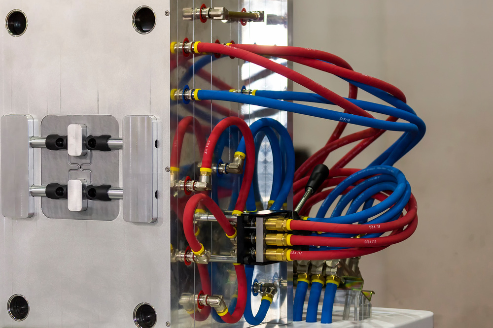
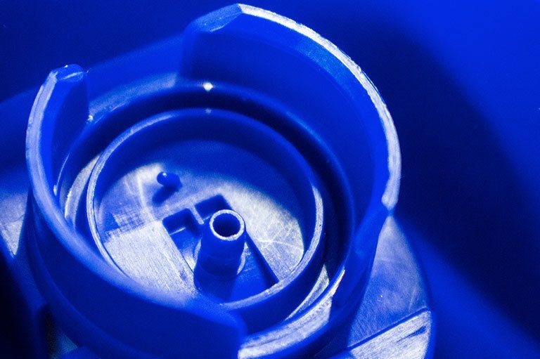
8. Cooling System Design
Proper cooling improves quality and reduces cycle time.
Design principles
- Cool uniformly across the part
- Cooling channels should be 1-2 × diameter apart
- Channel diameter = 0.125-0.5 inches
- Maintain 0.1-0.2 inch distance from cavity surface
Cooling types
- Water cooling: Most common, efficient
- Oil cooling: For high temperature materials
- Baffle cooling: For deep cavities
- Sprue cooling: For large gates
Benefits
- Reduces cycle time
- Improves part dimensional stability
- Minimizes warping and distortion
- Increases production efficiency
9. Tolerance Design
Specify realistic tolerances.
Standard tolerances
- SPI mold classes: SPI 1 (tightest) to SPI 5 (loosest)
- Typical tolerance: ±0.002-0.005 inches per inch
- Smaller parts: Tighter tolerances possible
Tolerance factors
- Material type affects achievable tolerance
- Part size: Larger parts have larger tolerances
- Feature location: Tolerances increase with distance
- Surface finish requirements
Cost considerations
- Tighter tolerances increase mold cost
- Only specify tight tolerances where needed
- Consider assembly requirements
10. Undercut Avoidance
Undercuts complicate mold design and increase cost.
What is an undercut?
- A feature that prevents straight ejection
- Examples: Threads, hooks, recesses
Design alternatives
- Use snap fits instead of threads
- Design parts to assemble after molding
- Use living hinges for flexible features
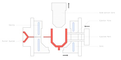
- Consider side actions if undercuts are necessary
When undercuts are needed
- Use side pulls or lifters
- Consider unscrewing mechanisms
- Be prepared for higher mold costs
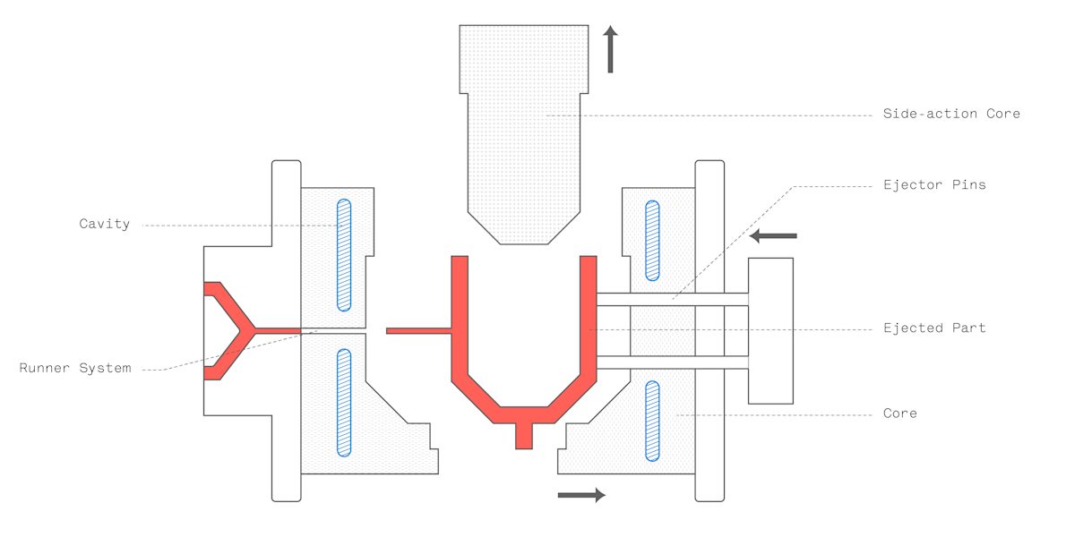
11. Mold Feasibility
Design parts that can be molded efficiently.
Mold structure considerations
- Avoid thin steel sections in molds
- Ensure adequate mold strength
- Consider mold cooling requirements
- Plan for easy maintenance
Parting line design
- Place parting lines where they won’t affect appearance
- Avoid complex parting lines when possible
- Consider flash removal requirements
Ejection system
- Design for balanced ejection
- Place ejector pins in non-critical areas
- Consider part ejection forces
12. Cost Considerations
Design for cost-effective production.
Material costs
- Minimize part weight
- Use standard materials when possible
- Consider material availability
Mold costs
- Simple designs cost less to tool
- Avoid complex features
- Consider production volume when designing
Production costs
- Design for fast cycle times
- Minimize post-processing requirements
- Consider automation potential
Total cost factors
- Initial tooling cost vs. production volume
- Material cost per part
- Labor and processing costs
- Quality and scrap rates

Design Checklist
Before finalizing your design:
✓ Check wall thickness uniformity
✓ Add proper draft angles
✓ Replace sharp corners with radii
✓ Design ribs correctly
✓ Select appropriate material
✓ Account for shrinkage
✓ Choose proper gate location
✓ Plan cooling system
✓ Specify realistic tolerances
✓ Avoid unnecessary undercuts
✓ Ensure mold feasibility
✓ Consider total costs
Common Design Mistakes
Avoid these common pitfalls:
❌ Uneven wall thickness
❌ Insufficient draft angles
❌ Sharp corners without radii
❌ Overly thick ribs
❌ Ignoring material shrinkage
❌ Poor gate placement
❌ Inadequate cooling design
❌ Unrealistic tolerances
❌ Unnecessary undercuts
❌ Complex mold requirements
❌ Overlooking production costs
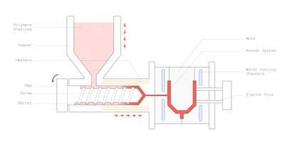
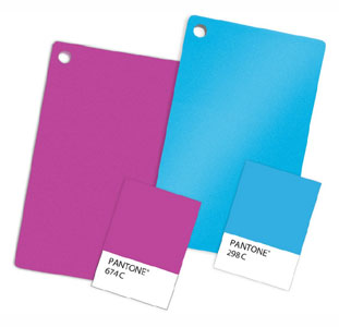
Material Color Selection
Choosing the right color is important for product appearance.
Color matching
- Use Pantone or RAL color standards
- Consider material transparency
- Test colors under different lighting conditions
Color stability
- Some colors fade in sunlight
- Consider outdoor exposure requirements
- Check material compatibility with colorants
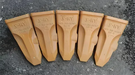
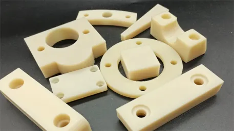
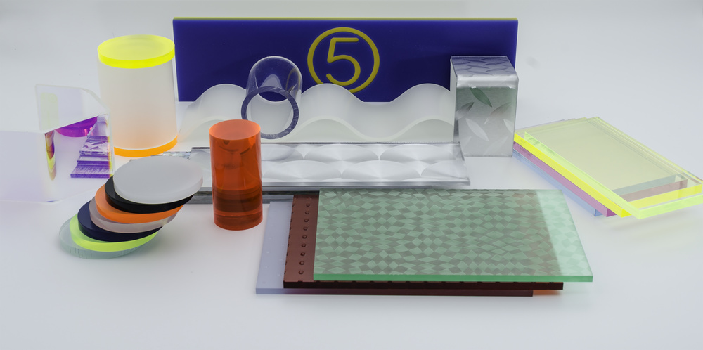
Plastic Material Samples
Visual reference of common plastic materials.
Material characteristics
- Color and transparency
- Surface finish options
- Texture possibilities
Sample testing
- Test mechanical properties
- Evaluate chemical resistance
- Check dimensional stability
This guide provides general design principles for injection molding. Always consult with experienced mold designers and manufacturers for specific applications and requirements.