I. Introduction
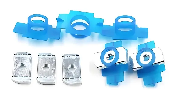
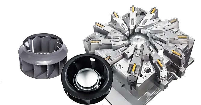
Special-shaped CNC parts usually have complex geometric shapes and strict precision requirements, and their processing process requires a high degree of technology and process knowledge. This technical guidance document will detail each link of the processing of special-shaped CNC parts, including process analysis, tool selection, programming strategies, cutting parameter settings, etc., and provide relevant data parameters as references to help you achieve high-quality and high-efficiency processing.
II. Part Analysis
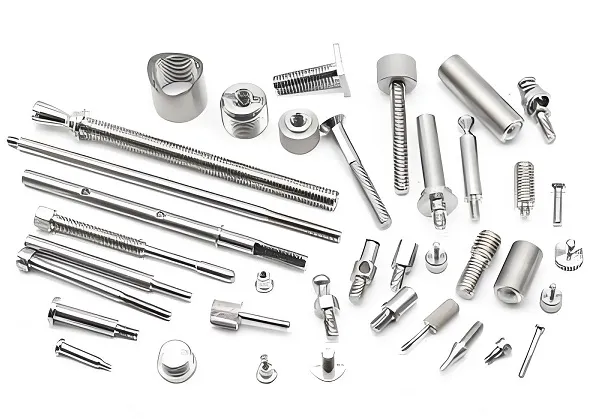
Carefully review the part drawing to understand the geometric shape, dimensional tolerance, surface roughness requirements, and functional requirements of the part.
Analyze the material properties of the part, such as hardness, strength, toughness, thermal conductivity, etc. Common materials for special-shaped parts include aluminum alloys (such as 7075, 6061), stainless steel (such as 304, 316), titanium alloys, etc.
III. Process Planning
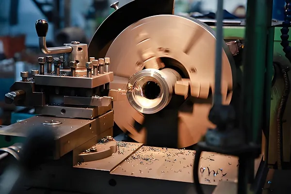
Machine Tool Selection
Based on the size, shape complexity, and precision requirements of the part, select the appropriate CNC machine tool. For example, for large special-shaped parts, gantry machining centers may be required; for parts with complex curved surfaces, five-axis machining centers may be more suitable.
Consider the parameters of the machine tool, such as stroke, spindle power, speed range, positioning accuracy, etc. Generally, the positioning accuracy of the machine tool should be within 0.01mm, and the repeat positioning accuracy should be within 0.005mm.
Process Route Formulation
Determine the processing sequence, usually following the principles of roughing first, then finishing, surface processing first, then hole processing, and main processing first, then secondary processing.
Reasonably divide the processing stages, including rough processing, semi-finishing processing, and finish processing. During rough processing, remove most of the allowance, and reserve an allowance of 0.5 – 1mm for semi-finishing processing; during semi-finishing processing, reduce the allowance to 0.1 – 0.3mm; during finish processing, meet the final dimensional and surface quality requirements.
IV. Tool Selection
Tool Material
Carbide tools: Suitable for most conventional processing, with good wear resistance and toughness.
Ceramic tools: Suitable for high-speed cutting of high-hardness materials, but with poor toughness.
Diamond tools: Used for processing high-hardness and high-precision parts, such as mirror processing of aluminum alloys.
Tool Geometry
For rough processing, select tools with large diameters, short cutting edges, and low helix angles to improve cutting efficiency.
During finish processing, use tools with small diameters, long cutting edges, and high helix angles to obtain good surface quality.
The parameters such as the rake angle, relief angle, and cutting edge inclination angle of the tool should be optimized according to the material and processing requirements. For example, when processing aluminum alloys, the rake angle of the tool can be selected between 15° – 25°, and when processing stainless steel, the rake angle can be selected between 8° – 15°.
Tool Coating
TiN (titanium nitride) coating: Improves the wear resistance and anti-adhesion of the tool.
TiAlN (titanium aluminum nitride) coating: Suitable for high-speed cutting and high-temperature environments.
DLC (diamond-like carbon) coating: Used to reduce the friction coefficient and improve the surface quality.
V. Cutting Parameter Settings
Cutting Speed (Vc)
Aluminum alloy: During rough processing, Vc can be between 300 – 800 m/min; during finish processing, Vc can reach 800 – 2000 m/min.
Stainless steel: During rough processing, Vc is approximately 80 – 150 m/min; during finish processing, Vc is 150 – 300 m/min.
Feed Rate (Vf)
During rough processing, Vf is usually between 0.1 – 0.3 mm/tooth; during finish processing, Vf is reduced to 0.05 – 0.15 mm/tooth.
Cutting Depth (ap)
During rough processing, ap can be between 2 – 5 mm; during semi-finishing processing, ap is 0.5 – 2 mm; during finish processing, ap is generally not more than 0.5 mm.
VI. Programming Strategies
Use CAM software (such as MasterCAM, UG, PowerMILL, etc.) for programming.
For complex special-shaped curved surfaces, strategies such as contour milling at equal height, streamline milling, and area milling can be used.
Optimize the tool path to reduce idle travel and tool lifting times and improve processing efficiency.
Consider tool radius compensation and length compensation to ensure processing accuracy.
VII. Clamping and Positioning
Select the appropriate fixture, such as vise, suction cup, special fixture, etc., to ensure the stability and accuracy of the part during processing.
Determine a reasonable positioning datum, follow the principle of datum coincidence, and reduce positioning errors.
For thin-walled parts, use auxiliary supports or add process bosses to prevent deformation.
VIII. Precautions During Processing
Monitor the cutting force, power, and temperature in real time to avoid overload and overheating.
Regularly check the tool wear and replace the severely worn tools in time.
Pay attention to the chip removal situation to prevent chip accumulation from affecting the processing quality and tool life.
IX. Quality Control
After processing, use measuring tools (such as calipers, micrometers, coordinate measuring machines, etc.) to measure the dimensions of the part.
Check the surface roughness of the part, and a roughness tester can be used for measurement.
For key parts, conduct non-destructive testing (such as flaw detection) to ensure there are no defects inside the part.
X. Conclusion
The processing of special-shaped CNC parts is a complex and precise process that requires comprehensive consideration of multiple factors and continuous optimization and adjustment according to the actual situation. Through reasonable process planning, tool selection, cutting parameter settings, and strict quality control, high-quality and high-efficiency processing of special-shaped parts can be achieved.