Introduction
Computer Numerical Control (CNC) technology has revolutionized modern manufacturing by enabling precise, automated control of machine tools through computer programs. This technology transforms digital designs into physical products with unprecedented accuracy and efficiency. Understanding the fundamental principles of CNC is essential for anyone involved in manufacturing, engineering, or related fields.
1. What is CNC?
1.1 Definition and Core Concept
CNC stands for Computer Numerical Control, a manufacturing method where computer programs control machine tools to create precision parts. Unlike traditional manual machining that relies on human operators, CNC systems use pre-programmed instructions to guide cutting tools and workpiece movements.
Key Characteristics:
- Automated Operation: Machines run unattended once programmed
- High Precision: Achieves tolerances as tight as ±0.001mm
- Repeatability: Consistent results across multiple parts
- Complex Geometry: Capable of producing intricate shapes
- Flexibility: Easy program changes for different parts
1.2 Evolution of CNC Technology
CNC technology has evolved significantly since its introduction in the 1950s:
Historical Development:
- 1950s: First CNC machines using vacuum tubes
- 1970s: Microprocessors revolutionize CNC systems
- 1990s: Windows-based interfaces and CAD/CAM integration
- 2000s: High-speed machining and 5-axis capabilities
- Today: Smart manufacturing and Industry 4.0 integration
2. CNC System Components
2.1 Hardware Components
Machine Tool Body:
- Bed and Frame: Provides structural rigidity
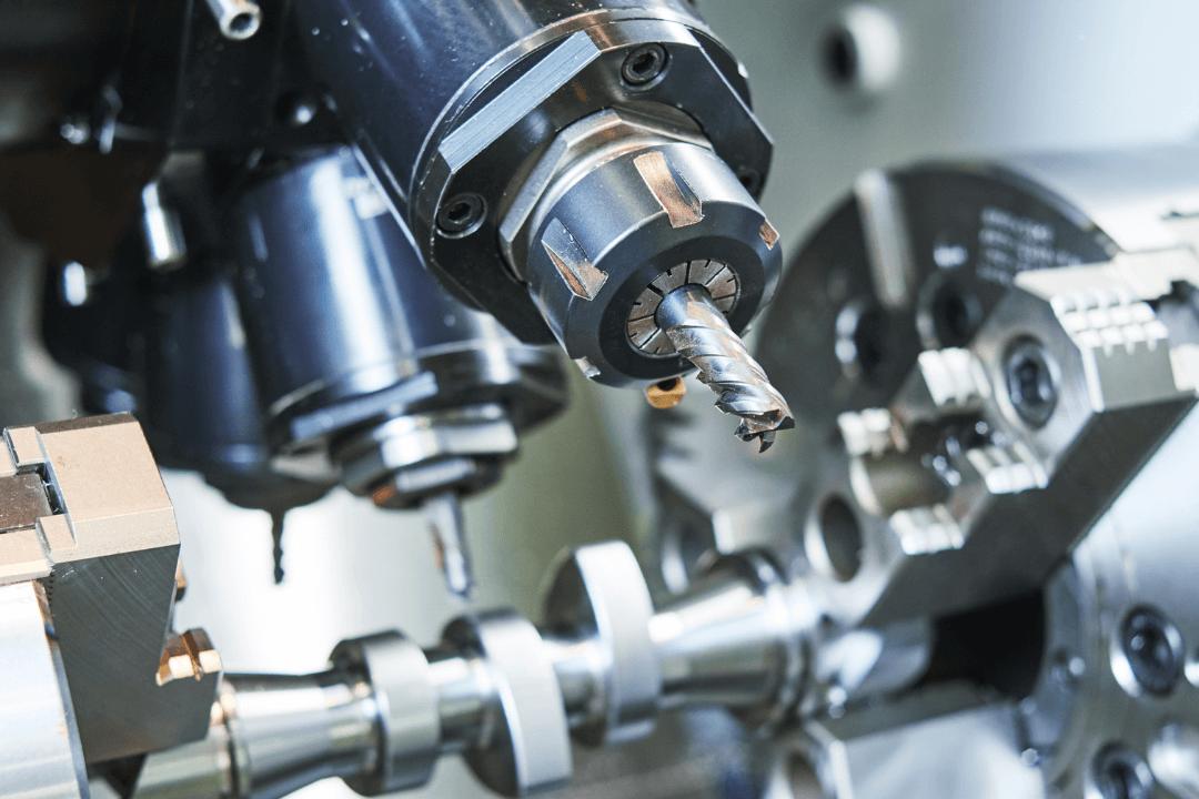
- Spindle: Rotates cutting tools at high speeds
- Worktable: Holds and positions the workpiece
- Guideways: Precision tracks for linear movement
- Feed Mechanisms: Translate motor motion to linear movement
Drive System:
- Servo Motors: Precise control of axis movements
- Stepper Motors: Cost-effective for simpler applications
- Ball Screws: Convert rotational motion to linear motion
- Linear Guides: Support and guide moving components
Control Panel:
- Operator Interface: Display screen and input devices
- Emergency Stop: Safety shutdown mechanism
- Manual Controls: Handwheels and buttons for setup
2.2 Control System
Machine Control Unit (MCU):
- Central Processing Unit (CPU): Main computer brain
- Memory: Stores programs and parameters
- Input/Output Interfaces: Connect to external devices
- Control Circuits: Regulate machine functions
Software Components:
- Operating System: Manages system resources
- Control Software: Executes machining programs
- User Interface: Programming and monitoring tools
- Diagnostic Tools: Troubleshooting and maintenance
2.3 Measurement and Feedback Systems
Position Feedback Devices:
- Encoders: Measure rotational position of motors
- Linear Scales: Directly measure linear movement
- Laser Interferometers: High-precision calibration tools
Closed-Loop Control:
- Real-time position monitoring
- Automatic error correction
- Improved accuracy and stability
3. CNC Working Principle
3.1 The CNC Process Flow
Step 1: Design (CAD)
- Create 2D or 3D digital model using Computer-Aided Design software
- Define dimensions, tolerances, and material specifications
- Ensure design is manufacturable (DFM principles)
Step 2: Programming (CAM)
- Convert CAD model to machine-readable code using Computer-Aided Manufacturing software
- Generate toolpaths, cutting parameters, and machining strategies
- Simulate and verify program to prevent errors
Step 3: Setup
- Mount workpiece securely on machine table
- Install appropriate cutting tools
- Set up fixtures and clamps
- Calibrate tool lengths and offsets
Step 4: Execution
- Load program into CNC controller
- Run program in single-block or automatic mode
- Monitor machining process
- Make adjustments as needed
Step 5: Inspection
- Measure finished part dimensions
- Check surface quality
- Verify tolerances are met
- Document results for quality control
3.2 Coordinate System Fundamentals
Machine Coordinate System:
- Fixed reference frame based on machine’s home position
- Absolute coordinates for all machine movements
- Consistent reference point for all operations
Workpiece Coordinate System:
- User-defined coordinate system relative to workpiece
- Multiple coordinate systems (G54-G59) for different setups
- Simplifies programming for complex parts
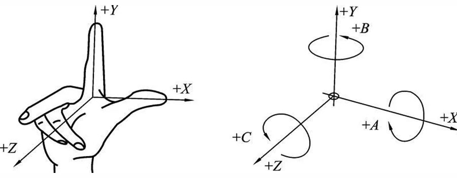
Axis Designations:
- X-Axis: Horizontal movement perpendicular to spindle
- Y-Axis: Horizontal movement perpendicular to X-axis
- Z-Axis: Vertical movement along spindle axis
- A, B, C Axes: Rotational axes for multi-axis machines
4. CNC Programming Languages
4.1 G-Code Fundamentals
G-Code (Preparation Function Codes) are the primary programming language for CNC machines, consisting of standardized commands that control machine movements and functions.
Basic G-Code Commands:
|
G-Code
|
Function
|
Description
|
|
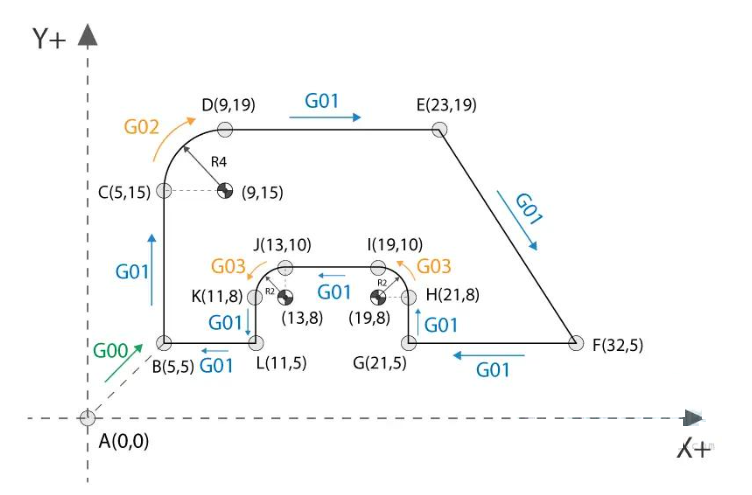
G00
|
Rapid Positioning
|
Fast movement to specified coordinates
|
|
G01
|
Linear Interpolation
|
Linear cutting movement at specified feed rate
|
|
G02
|
Circular Interpolation (Clockwise)
|
Circular cutting in clockwise direction
|
|
G03
|
Circular Interpolation (Counterclockwise)
|
Circular cutting in counterclockwise direction
|
|
G20
|
Inch Units
|
Set units to inches
|
|
G21
|
Metric Units
|
Set units to millimeters
|
|
G28
|
Return to Home Position
|
Move to machine reference position
|
|
G40
|
Tool Radius Compensation Cancel
|
Disable tool radius compensation
|
|
G41
|
Tool Radius Compensation Left
|
Enable left compensation
|
|
G42
|
Tool Radius Compensation Right
|
Enable right compensation
|
|
G54-G59
|
Work Offset Selection
|
Select workpiece coordinate system
|
|
G90
|
Absolute Positioning
|
Use absolute coordinates
|
|
G91
|
Incremental Positioning
|
Use incremental coordinates
|
|
G94
|
Feed Rate per Minute
|
Set feed rate in mm/min or in/min
|
|
G95
|
Feed Rate per Revolution
|
Set feed rate in mm/rev or in/rev
|
4.2 M-Code Functions
M-Codes (Miscellaneous Function Codes) control auxiliary functions of the CNC machine:
|
M-Code
|
Function
|
Description
|
|
M00
|
Program Stop
|
Pause program execution
|
|
M01
|
Optional Stop
|
Pause if optional stop button is active
|
|
M02
|
Program End
|
End of program, no return to start
|
|
M30
|
Program End and Reset
|
End program and return to start
|
|
M03
|
Spindle Forward
|
Start spindle clockwise rotation
|
|
M04
|
Spindle Reverse
|
Start spindle counterclockwise rotation
|
|
M05
|
Spindle Stop
|
Stop spindle rotation
|
|
M08
|
Coolant On
|
Start coolant flow
|
|
M09
|
Coolant Off
|
Stop coolant flow
|
|
M30
|
Program End and Reset
|
End program and reset to start
|
|
M6
|
Tool Change
|
Automatic tool change
|
4.3 Other Important Codes
S-Code: Spindle Speed Control
- Format: Sxxxx (e.g., S3000 = 3000 RPM)
- Controls rotational speed of spindle
F-Code: Feed Rate Control
- Format: Fxxxx (e.g., F200 = 200 mm/min)
- Controls cutting speed of tool
T-Code: Tool Selection
- Format: Txx (e.g., T03 = Tool 3)
- Selects specific tool from tool magazine
5. CNC Machine Types
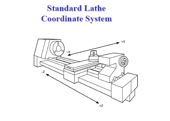
5.1 CNC Lathes
CNC lathes are used for machining cylindrical parts by rotating the workpiece while cutting tools move linearly.
Key Features:
- Spindle: Rotates workpiece at high speeds
- Turret: Holds multiple cutting tools
- Chuck: Secures workpiece
- Tailstock: Supports long workpieces
Common Applications:
- Shafts and rods
- Threaded components
- Cylindrical parts
- Contoured surfaces
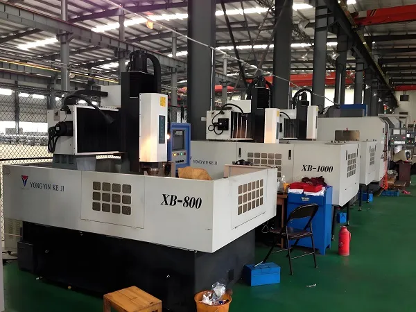
5.2 CNC Milling Machines
CNC milling machines use rotating cutting tools to remove material from stationary workpieces.
Key Features:
- Spindle: Rotates cutting tools
- Worktable: Moves in X, Y, Z axes
- Tool Changer: Automatic tool exchange
- Coolant System: Controls cutting temperatures
Common Applications:
- Flat surfaces
- Complex 3D shapes
- Slots and pockets
- Custom components
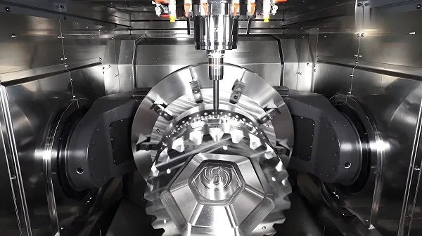
5.3 Multi-Axis Machines
Advanced CNC machines with 4, 5, or more axes enable complex geometry machining.
5-Axis Machining:
- X, Y, Z Axes: Linear movements
- A, B Axes: Rotational movements
- Capabilities: Complex 3D shapes in single setup
- Applications: Aerospace, medical, mold making
5.4 Specialized CNC Machines
CNC Grinding Machines:
- High-precision surface finishing
- Tight tolerances (±0.0001mm)
- Applications: Tool and die making
CNC Laser Cutting Machines:
- Non-contact cutting
- High precision and speed
- Applications: Sheet metal, plastics
CNC Electrical Discharge Machines (EDM):
- Machining hard materials
- Complex shapes and fine details
- Applications: Mold making, aerospace
6. Advantages of CNC Machining
6.1 Precision and Accuracy
Key Benefits:
- Tight Tolerances: Achieves ±0.001mm or better
- Consistency: Parts are identical batch to batch
- Repeatability: Same results every time
- Reduced Human Error: Automated operation minimizes mistakes
6.2 Efficiency and Productivity
Performance Improvements:
- 24/7 Operation: Unattended machining
- Faster Setup: Quick program changes
- Reduced Scrap: Precise material usage
- Higher Cutting Speeds: Advanced toolpath strategies
6.3 Flexibility and Versatility
Adaptability Features:
- Quick Changeover: Program changes instead of mechanical adjustments
- Multiple Part Types: Same machine for different components
- Complex Shapes: Capable of intricate geometries
- Prototype to Production: Seamless transition
6.4 Cost Savings
Economic Benefits:
- Reduced Labor Costs: Less operator involvement
- Lower Scrap Rates: Precision machining
- Increased Throughput: Higher production rates
- Longer Tool Life: Optimized cutting parameters
7. Applications of CNC Technology
7.1 Aerospace Industry
Critical Applications:
- Engine Components: Turbine blades, casings
- Structural Parts: Wing components, landing gear
- Precision Requirements: ±0.001mm tolerances
- Materials: Titanium, aluminum, composites
7.2 Automotive Industry
Production Applications:
- Engine Parts: Blocks, heads, crankshafts
- Transmission Components: Gears, shafts, housings
- Mass Production: High-volume manufacturing
- Quality Standards: IATF 16949 compliance
7.3 Medical Device Manufacturing
Precision Requirements:
- Implants: Hip, knee, dental implants
- Surgical Instruments: Scalpels, forceps
- Biocompatible Materials: Titanium, stainless steel
- Regulatory Compliance: FDA, ISO 13485
7.4 Electronics Industry
Miniaturization Needs:
- Components: Connectors, heat sinks
- Enclosures: Phone cases, computer parts
- Precision: Micro-machining capabilities
- Materials: Aluminum, plastics, brass
7.5 Tool and Die Making
Specialized Applications:
- Molds: Injection, blow molding
- Dies: Stamping, forging
- High Precision: Tight tolerance requirements
- Customization: One-of-a-kind tools
8. CNC Programming Methods
8.1 Manual Programming
Traditional Approach:
- Direct G-code programming at machine control panel
- Best for simple parts and small production runs
- Requires deep understanding of G-code and machine capabilities
- Limited to basic geometries
Advantages:
- Quick for simple parts
- No additional software needed
- Good for manual adjustments
Disadvantages:
- Time-consuming for complex parts
- Prone to programming errors
- Limited to experienced programmers
8.2 Computer-Aided Programming (CAM)
Modern Approach:
- Use CAM software to generate G-code from CAD models
- Automatic toolpath generation
- Simulation and verification capabilities
- Support for complex geometries
Popular CAM Software:
- Mastercam: Widely used in industry
- SolidWorks CAM: Integrated with SolidWorks
- UG NX CAM: High-end manufacturing solution
- Fusion 360: Cloud-based CAD/CAM
- BobCAD-CAM: Cost-effective solution
Advantages:
- Faster programming for complex parts
- Reduced errors through simulation
- Support for advanced machining strategies
- Integration with CAD systems
8.3 Conversational Programming
User-Friendly Approach:
- Graphical interface for programming
- Menu-driven input of dimensions and parameters
- No G-code knowledge required
- Good for simple to moderate complexity parts
Applications:
- Small job shops
- Prototyping
- Simple part production
- Operator-friendly environments
9. Quality Control in CNC Machining
9.1 Inspection Tools and Methods
Precision Measurement:
- Coordinate Measuring Machine (CMM): 3D measurement of complex parts
- Optical Comparator: 2D profile measurement
- Micrometers and Calipers: Basic dimensional measurement
- Surface Roughness Tester: Ra, Rz measurements
- Tool Presetter: Tool length and diameter measurement
In-Process Monitoring:
- Force Sensors: Detect tool wear and breakage
- Temperature Sensors: Monitor cutting temperatures
- Vibration Analysis: Detect machine instability
- Vision Systems: Real-time part inspection
9.2 Statistical Process Control (SPC)
Quality Assurance Method:
- Monitor process variation
- Detect trends and anomalies
- Prevent defects before they occur
- Continuous improvement
Key Metrics:
- Cp/Cpk: Process capability indices
- Control Charts: X-bar, R-chart, S-chart
- Process Variation: Standard deviation, range
- Defect Rates: PPM (parts per million)
9.3 Tolerance Standards
Industry Standards:
- ISO Tolerance Grades: IT01 to IT18
- ANSI B4.1: American standard for limits and fits
- DIN 7168: German tolerance standard
- JIS B 0401: Japanese tolerance standard
Common Tolerances:
- Rough Machining: ±0.1mm to ±0.05mm
- Finish Machining: ±0.05mm to ±0.01mm
- Precision Machining: ±0.01mm to ±0.001mm
- Ultra-Precision: ±0.001mm or better
10. Future Trends in CNC Technology
10.1 Industry 4.0 Integration
Smart Manufacturing:
- Internet of Things (IoT): Connected machines and devices
- Big Data Analytics: Process optimization through data
- Artificial Intelligence: Predictive maintenance, quality control
- Digital Twin: Virtual simulation of machines and processes
Benefits:
- Increased productivity
- Predictive maintenance
- Real-time monitoring
- Remote diagnostics
10.2 Advanced Machining Technologies
High-Speed Machining:
- Spindle speeds up to 60,000 RPM
- Higher feed rates and material removal rates
- Improved surface finish
- Reduced cycle times
Additive Manufacturing Integration:
- Hybrid machines combining additive and subtractive processes
- 3D printing for complex geometries
- CNC machining for precision finishing
- Rapid prototyping and small production runs
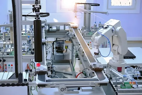
10.3 Automation and Robotics
Factory Automation:
- Robotic Loading/Unloading: 24/7 operation
- Automated Guided Vehicles (AGVs): Material transport
- Flexible Manufacturing Systems (FMS): Integrated production lines
- Cobots: Collaborative robots working with humans
10.4 Sustainability in Manufacturing
Green Technologies:
- Energy Efficiency: Low-power machine designs
- Coolant Recycling: Reduced environmental impact
- Waste Reduction: Precision machining minimizes scrap
- Material Recycling: Metal recycling programs
Conclusion
CNC technology has transformed manufacturing by combining computer control with precision machining to produce high-quality parts efficiently and consistently. Understanding the fundamental principles of CNC—from system components and working principles to programming languages and applications—is essential for anyone working in modern manufacturing.
The key takeaways from this guide include:
Core Principles:
- CNC systems use computer programs to control machine tools
- Precision, repeatability, and automation are defining characteristics
- Coordinate systems and programming languages enable complex machining
Technical Knowledge:
- Understanding of G-code and M-code programming
- Familiarity with different CNC machine types and their applications
- Knowledge of quality control methods and tolerance standards
Practical Applications:
- CNC technology is used across industries from aerospace to medical
- Programming methods range from manual to advanced CAM software
- Future trends include Industry 4.0, AI integration, and sustainability
As manufacturing continues to evolve, CNC technology will remain at the forefront of innovation, enabling new capabilities and applications. By mastering the fundamental principles outlined in this guide, you’ll be well-positioned to leverage the power of CNC in your work or studies.
Frequently Asked Questions (FAQ)
Q: What is the difference between CNC and conventional machining?
A: CNC machining uses computer programs to automate machine tool control, while conventional machining relies on manual operation. CNC offers higher precision, repeatability, and efficiency.
Q: How difficult is it to learn CNC programming?
A: Basic G-code programming can be learned in a few weeks, but mastering advanced programming and CAM software takes months of practice. The learning curve depends on the complexity of parts being produced.
Q: What are the most common CNC machine types?
A: The most common types are CNC lathes (for cylindrical parts) and CNC milling machines (for flat and complex shapes). Other types include 5-axis machines, grinders, and laser cutters.
Q: What software is used for CNC programming?
A: Popular CAM software includes Mastercam, SolidWorks CAM, UG NX CAM, Fusion 360, and BobCAD-CAM. These programs convert CAD models into machine-readable G-code.
Q: What tolerances can CNC machines achieve?
A: Standard CNC machines achieve ±0.01mm to ±0.005mm tolerances. High-precision machines can reach ±0.001mm or better for specialized applications.
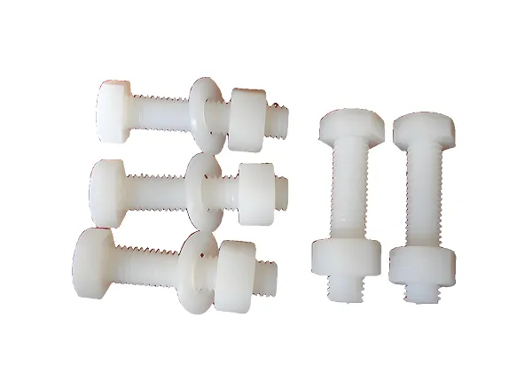
Q: What materials can be machined with CNC?
A: CNC machines can process metals (aluminum, steel, titanium), plastics (ABS, PVC, PEEK), composites, wood, and even some ceramics, depending on the machine type.
Q: How much does a CNC machine cost?
A: CNC machine costs range from (10,000 for small benchtop machines to )1 million or more for large, advanced 5-axis machining centers.
Q: What skills are needed to work with CNC machines?
A: Skills include understanding of machining principles, G-code programming, CAD/CAM software, blueprint reading, metrology, and basic machine maintenance.
Q: What is the future of CNC technology?
A: The future includes Industry 4.0 integration, AI and machine learning, increased automation, additive manufacturing combination, and greater sustainability.
Q: How important is CNC in modern manufacturing?
A: CNC is essential in modern manufacturing, enabling high-precision, efficient production across industries. It’s the foundation for advanced manufacturing technologies and Industry 4.0.
Disclaimer
- All information, opinions, and data contained in this article are for the purpose of information transmission only and do not constitute any advice on investment, transactions, law, medical care, or other matters.
- The content of the article is compiled based on public information or created based on the author’s personal understanding. Although every effort is made to ensure accuracy, it does not guarantee the completeness, accuracy, and timeliness of the information, nor does it bear any responsibility for any losses caused by the use of the content of this article.
- If the article involves third-party opinions, pictures, data, and other content, the copyright belongs to the original author. In case of infringement, please contact us for deletion.
- Readers should make independent decisions based on their actual situation and combined with professional opinions. The user shall bear all consequences arising from the use of the content of this article.
Understanding CNC: Fundamental Principles of Computer Numerical Control
For more information on CNC technology or to discuss specific applications, contact our technical team today.