Performance Characteristics of Contour Line Machining
Accuracy and Precision
Contour line machining offers exceptional accuracy:
- Dimensional accuracy: Typically ±0.01mm to ±0.05mm depending on machine capability
- Form accuracy: Maintains complex surface profiles within tight tolerances
- Positioning accuracy: Consistent layer heights ensure uniform material removal
Dr. James Miller, Manufacturing Technology Expert at MIT:
“Contour line machining provides superior form accuracy compared to other strategies because it directly follows the mathematical definition of the surface. This makes it indispensable for precision applications like aerospace components and medical devices.”
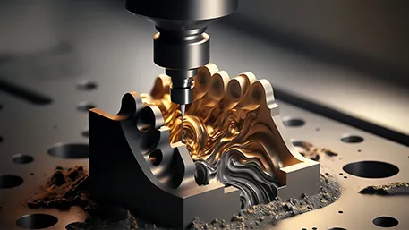
Surface Quality
The surface finish achievable with contour line machining is excellent:
- Surface roughness: Ra 0.4-3.2 μm depending on stepover and tool geometry
- Scallop height: Directly related to stepover distance and surface curvature
- Texture uniformity: Consistent finish across the entire machined surface
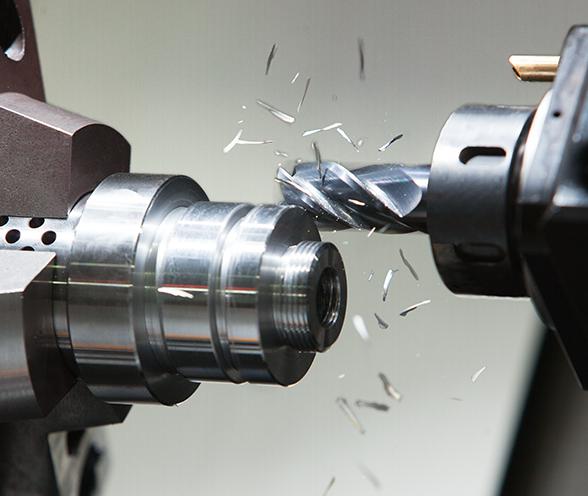
Material Removal Efficiency
While not the fastest strategy for all applications, contour line machining offers:
- Predictable material removal: Consistent chip load per tooth
- Reduced tool wear: Stable cutting conditions minimize wear
- Process reliability: Lower risk of tool breakage compared to aggressive strategies
Applications of Contour Line Machining
Primary Application Areas
Contour line machining is particularly suited for:
1. Mold and Die Manufacturing
- Cavity and core machining: Complex mold surfaces with tight tolerances
- Draft angles: Maintaining consistent angles across large surfaces
- Textured surfaces: Creating uniform surface textures
2. Aerospace Industry
- Turbine blades: Complex aerodynamic profiles
- Structural components: Wing spars and fuselage parts
- Engine components: Compressor and turbine casings
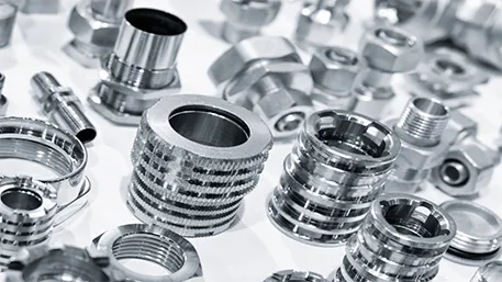
3. Medical Device Manufacturing
- Implants: Hip, knee, and spinal implants with complex geometries
- Surgical instruments: Precision cutting tools and handles
- Diagnostic equipment: Imaging device components
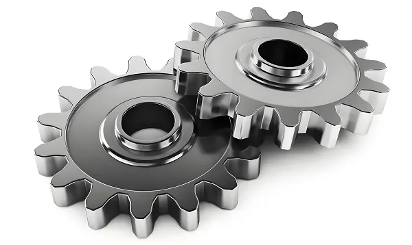
4. Automotive Industry
- Intake manifolds: Complex internal passages
- Gearbox components: Housing and cover parts
- Custom prototypes: Rapid development of new designs
Case Study: Aerospace Turbine Blade Machining
A leading aerospace manufacturer implemented contour line machining for turbine blade production:
- Challenge: Machining complex aerodynamic surfaces with tight tolerances
- Solution: 5-axis contour line machining with adaptive stepover
- Results:
-
- Surface finish improved from Ra 1.6 μm to Ra 0.8 μm
-
- Production time reduced by 35%
-
- Tool life increased by 40%
-
- Scrap rate decreased from 8% to 2%
Comparison with Other Machining Strategies
Contour Parallel vs. Radial Machining
|
Characteristic
|
Contour Parallel (Contour Lines)
|
Radial Machining
|
|
Path Geometry
|
Parallel curves following contours
|
Spiral from center outward
|
|
Surface Finish
|
Excellent, uniform
|
Good, potential center defects
|
|
Tool Engagement
|
Consistent, stable
|
Varies with radius
|
|
Complexity Handling
|
Excellent for complex shapes
|
Better for circular features
|
|
Programming Complexity
|
Moderate
|
Low
|
|
Best Applications
|
Complex 3D surfaces
|
Circular pockets, flat surfaces
|
Contour Lines vs. Adaptive Clearing
|
Characteristic
|
Contour Lines
|
Adaptive Clearing
|
|
Material Removal Rate
|
Moderate
|
High
|
|
Tool Wear
|
Low
|
Moderate to high
|
|
Surface Quality
|
Excellent
|
Good to very good
|
|
Roughing Efficiency
|
Lower
|
Higher
|
|
Finishing Capability
|
Excellent
|
Good
|
|
Best Use
|
Finishing operations
|
Roughing operations
|