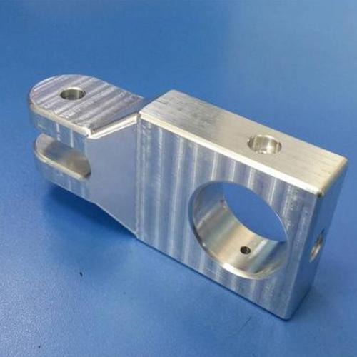
CNC prototype machined parts are product prototype components manufactured through Computer Numerical Control (CNC) technology, used to verify design feasibility in the product development stage. The core process involves transforming 3D CAD models into G-code instructions to drive CNC machines (such as machining centers and lathes) for subtractive manufacturing—milling, turning, etc.—on metals (aluminum alloy, stainless steel, etc.) or engineering plastics (ABS, nylon, etc.), rapidly producing physical parts. These parts feature high precision (tolerance within ±0.05mm) and material properties close to finished products, directly applicable for functional testing, assembly verification, and appearance evaluation. They efficiently bridge design concepts to physical entities, especially suitable for prototyping complex structures with strict precision requirements.
I. Technical Principles and CNC Machining Logic
1. Digital-Driven Technical Framework
CNC prototype machining follows the technical 主线 of “digital model-instruction conversion-physical forming”:
CNC prototype machining follows the technical 主线 of “digital model-instruction conversion-physical forming”:
- CAD Modeling: Construct 3D models using SolidWorks, UG, etc., with complete dimensional tolerances and surface roughness requirements.
- CAM Programming: Convert models into tool paths via software like Mastercam, generating G-codes (e.g., G01 linear interpolation, G02 arc command) to control machine movements.
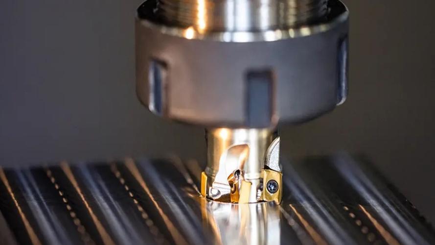
- CNC Execution: The machine’s servo system controls tool movements along X/Y/Z axes per instructions, removing materials through milling, drilling, etc., to form prototype parts.
2. Technical Differences from 3D Printing
| Comparison Dimension | CNC Machining Technology | 3D Printing Technology |
|---|---|---|
| Forming Method | Subtractive manufacturing (material removal) | Additive manufacturing (material stacking) |
| Precision | ±0.02-0.05mm | ±0.1-0.3mm (FDM process) |
| Material Properties | Density close to finished products, superior mechanical properties | Possible internal pores, lower strength |
| Complex Structures | Undercuts require disassembly for machining | Direct forming of hollow structures |
II. Analysis of the Complete Process Flow
1. Pre-Process Planning
- Machinability Analysis: Check for areas unreachable by tools (e.g., blind holes with depth-diameter ratio >5:1), and split complex structures into machinable units.
- Fixture Design: Clamp small parts with vices; customize fixtures for large metal parts (e.g., vacuum adsorption fixtures for automotive panel prototypes) to ensure sufficient rigidity.
2. Execution of Cutting Processes
- Rough Machining: Use large-diameter tools (e.g., φ16mm end mill) to quickly remove stock, leaving 1-2mm allowance, at feed rates of 1000-1500mm/min.
- Finishing Machining: Switch to small tools (e.g., φ3mm ball end mill) for surface refinement, controlling tolerance within ±0.03mm and surface roughness Ra≤1.6μm.
3. Post-Processing
- Surface Treatment: Anodize aluminum alloys, electroplate for rust prevention, or paint plastic parts for appearance;
- Stress Relief: Age anneal titanium alloy parts to eliminate cutting stress and prevent deformation.
III. Technical Terms and Concepts
| Term | Definition and Application Scenario |
|---|---|
| Tool Compensation | Correct tool radius wear via G41/G42 commands, ensuring contour accuracy—e.g., real-time offset correction for 0.5mm thin-walled parts. |
| Three Cutting Elements | Spindle speed (rpm), feed rate (mm/min), cutting depth—control speed at 1500-2000rpm for stainless steel to prevent tool overheating. |
| Workholding Fixtures | Special devices to fix workpieces—e.g., positioning pins and clamp combinations for engine block prototypes, ensuring hole pattern positional tolerance ≤0.05mm. |
| Tolerance Zone | Allowed dimension variation range—e.g., H7/g6 tolerance zone for shaft-hole fits, ensuring assembly clearance of 0.02-0.06mm. |
| CMM Measurement | Use Coordinate Measuring Machines to inspect parts—e.g., key hole spacing in automotive knuckle prototypes controlled within ±0.02mm. |
IV. Machining Capabilities and Part Characteristics
1. Adaptability to Part Structures
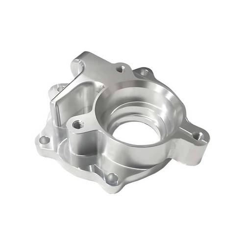
- Complex Geometry Machining: Five-axis machines can machine twisted profiles of aero-engine blades, achieving a minimum fillet radius of 0.2mm via “side milling”;
- Precision Hole Machining: CNC drills can produce φ0.8mm micro-through holes with perpendicularity ≤0.03mm (e.g., medical syringe valve prototypes).
2. Material-Performance Matching
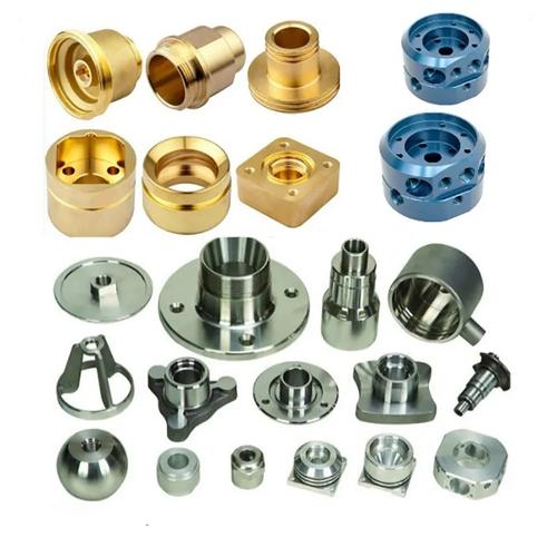
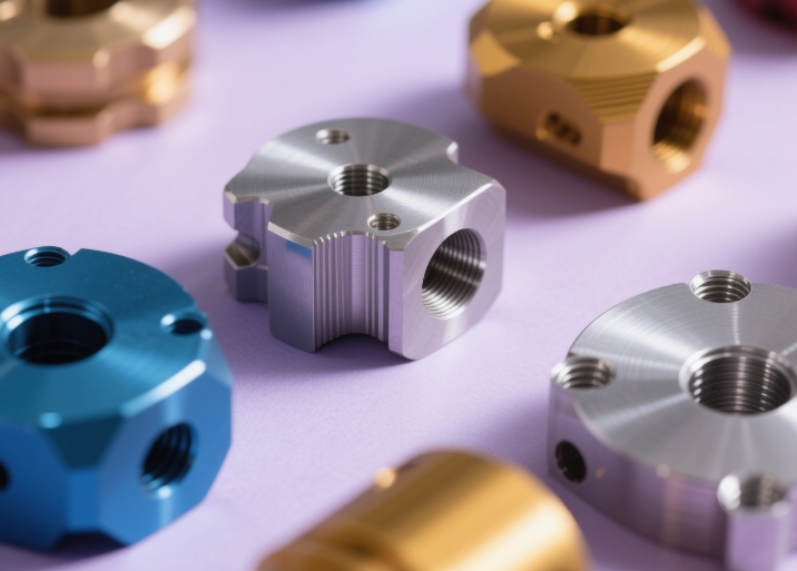
- Metal Parts:
- Aluminum 6061: 310MPa tensile strength, suitable for lightweight automotive structure prototypes;
- Stainless Steel 316L: High corrosion resistance for medical device prototypes (e.g., surgical forceps).
- Plastic Parts:
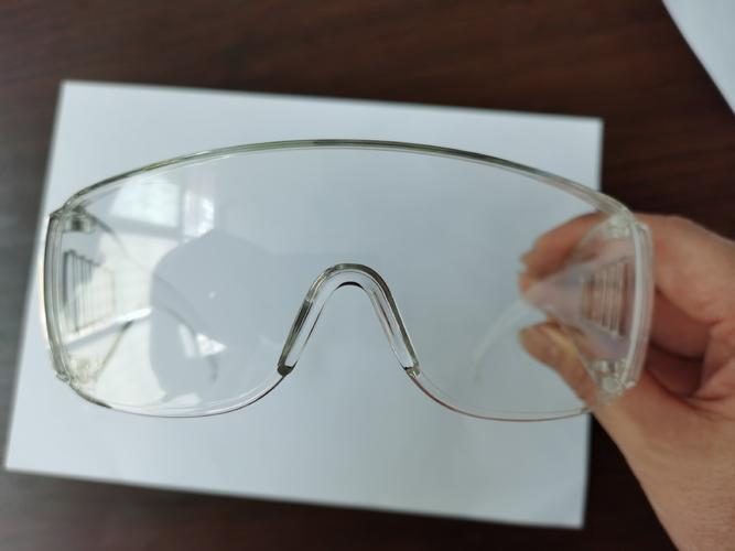
- PC (Polycarbonate): High impact strength for protective housing prototypes;
- POM (Acetal): Good wear resistance for moving parts like gears and bearings.
V. Part Applications and Verification Scenarios
1. Functional Testing Scenarios
- Moving Component Verification: CNC-machined gear prototypes undergo running-in tests to check tooth surface contact accuracy (contact area ≥70%);
- Fluid Performance Testing: CNC-machined water pump impeller prototypes undergo hydrostatic tests (5MPa pressure) for sealing verification.
2. Typical Parts in Industries
- Automotive Field:
- Engine cylinder head prototypes: Machined φ55mm valve holes with cylindricity ≤0.015mm;
- Interior parts prototypes: Assembly hole positional tolerance ≤0.1mm for seamless dashboard 对接.
- Aerospace:
- Satellite bracket prototypes: Ti-6Al-4V titanium alloy, weight error ≤0.5%, dimensional tolerance ±0.03mm;
- Consumer Electronics:
- Mobile phone middle frame prototypes: 7075 aluminum alloy, 0.3mm ultra-thin frame via CNC milling, surface roughness Ra≤0.8μm.
Conclusion
CNC prototype machined parts, centered on numerical control technology, achieve transformation from digital models to high-precision entities through precise process planning and cutting control. Their technical advantages lie in machining accuracy, material properties, and functional verification capabilities. From automotive engine blocks to medical minimally invasive instruments, these parts continuously support design iteration in product development, serving as an indispensable prototyping means in high-end manufacturing.