Answer
The four basic types of metal stamping are blanking, bending, drawing, and forming.
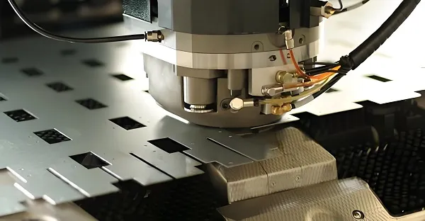
- Blanking: Separates materials along a predetermined contour using dies, including punching (removing waste) and blanking (obtaining the workpiece). It is used to manufacture flat parts such as gaskets and flange blanks.
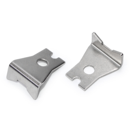
- Bending: Forms sheet metal into specific angles or shapes under bending moment, such as U-shaped, V-shaped, and Z-shaped bends. It applies to parts with bending structures like brackets and automotive door frames.
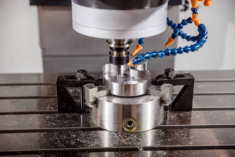
- Drawing: Converts flat sheets into open hollow parts using punch and die, such as cylindrical, box-shaped, or conical workpieces. Common applications include producing cups, fuel tanks, and instrument casings.
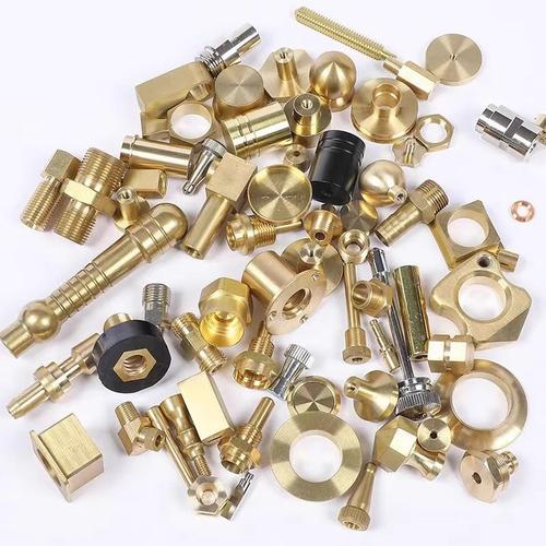
- Forming: Alters material shape through local deformation, including flanging, bulging, necking, embossing, and spinning. It is used for processing complex curved structures like stiffening ribs, bosses, and bellows.
Extended Explanation: Detailed Analysis of Four Metal Stamping Types
(1) Blanking Process: The Basic Technology for Material Separation
1. Process Principle and Core Mechanism
Blanking is a process where materials crack and separate under shear and tensile forces due to the clearance between the punch and die edges. Its essence is fracture separation of sheet metal, divided into three stages:
- Elastic Deformation Stage: The punch contacts the material, causing elastic compression and bending of the sheet.
- Plastic Deformation Stage: Stress exceeds the yield strength, generating micro-cracks near the edges.
- Fracture Separation Stage: Cracks propagate through the material, completing separation.
2. Key Classifications and Technical Features
|
Classification
|
Technical Points
|
Typical Applications
|
|
Common Blanking
|
Large edge clearance (5%-10% of material thickness), with three-section fracture surface (rounding zone, burnished zone, fracture zone), accuracy IT12-IT14.
|
Gaskets, flanges, simple contour parts.
|
|
Precision Blanking
|
Uses negative-clearance die and V-shaped ring blank holder, clearance < 1% of material thickness, fracture surface perpendicularity 90°, accuracy IT6-IT8.
|
Gears, bearing cages, precision parts.
|
|
Trimming Blanking
|
Second-stage cutting of common blanking edges to remove the fracture zone and improve dimensional accuracy and surface quality.
|
High-precision hole machining, aerospace parts.
|
3. Core Elements of Die Design
- Clearance Control: Excessive clearance causes burrs; insufficient clearance leads to die cracking. Adjust according to material plasticity (e.g., 8%-12% thickness for stainless steel).
- Edge Form: Punches can be stepped (for multi-punch blanking) or oblique-edged (reducing blanking force); dies are usually integral or mosaic (for large parts).
- Unloading and Ejection: Uses elastic stripper plates or rigid ejectors to prevent waste blockage and ensure safety.
4. Material Adaptability and Defect Handling
- Suitable Materials: Ductile metals like low-carbon steel (Q235), aluminum alloy (5052), and brass (H62), typically with thickness ≤6mm.
- Common Defects:
- Excessive Burrs: Adjust clearance and grind edges.
- Hole Edge Tearing: Check positioning accuracy and replace worn dies.
- Dimensional Deviation: Correct punch/die manufacturing tolerances (usually 1/3 of workpiece tolerance).
(2) Bending Process: Three-dimensional Shaping via Linear Deformation
1. Deformation Principle and Stress Distribution
During bending, the inner material is compressed, and the outer material is stretched, with the neutral layer (zero stress) position changing with the bending radius. Key parameters include:
- Bending Radius R: R ≥ (0.25-1) t (t = material thickness); too small radius causes outer cracking.
- Bending Central Angle α: Determines bending degree and affects springback (Δα = α_unloading – α_loading).
2. Main Bending Forms and Equipment
3. Springback Control Techniques
Springback is the main challenge in bending, controlled by:
- Die Compensation: Reduce punch angle by Δα (springback angle) or design negative-clearance dies.
- Correction Bending: Increase material compaction by the punch to tension the inner neutral layer.
- Hot Bending: Heat materials like titanium alloy to recrystallization temperature (e.g., TC4 at 600℃) to reduce elastic modulus.
4. Die Structure and Process Optimization
- Positioning Design: Uses stop pins, positioning plates, or vacuum adsorption to prevent material sliding during bending.
- Anti-wrinkling Measures: Employs elastic blank holders for thin materials (t < 1mm) to suppress inner wrinkling.
- Automation Application: CNC bending machines with laser angle sensors real-time correct springback deviation, achieving accuracy ±0.5°.
(3) Drawing Process: The Mystery of Hollow Part Formation
1. Deformation Process and Zone Division
Drawing converts flat sheets into hollow parts through plastic deformation, with material experiencing radial tension and tangential compression. It is divided into three deformation zones:
- Flange Zone: Main deformation zone, with tangential compressive stress risking wrinkling.
- Wall Zone: Force-transmitting zone, tensile stress, prone to tearing.
- Bottom Radius Zone: Transition zone, with maximum thickness reduction (up to 30%).
2. Key Process Parameters
- Drawing Ratio m: m = d/D (d = workpiece diameter, D = blank diameter), first drawing m ≥ 0.5-0.8 (decreases with higher material ductility).
- Blank Holder Force F: Prevents flange wrinkling, F = A・q (A = flange area, q = unit blank holder force, 25-35MPa for stainless steel).
- Die Clearance Z: Z = (1.1-1.2) t; excessive clearance causes wall thickness unevenness; insufficient clearance increases drawing force.
3. Drawing Types and Application Scenarios
|
Drawing Category
|
Technical Features
|
Typical Products
|
|
First Drawing
|
Directly forms hollow parts from flat sheets, suitable for shallow drawing (h/d ≤ 0.3, h = height).
|
Beverage cans, cosmetic boxes
|
|
Multiple Drawing
|
Uses multi-stage dies to gradually reduce diameter and increase height, requiring intermediate annealing to eliminate work hardening (e.g., steel at 650℃).
|
Automotive body panels, cartridge cases
|
|
Ironing Drawing
|
Clearance Z < t, mainly changing wall thickness with minimal diameter change, for ultra-thin-walled parts (e.g., mobile phone battery cases, t = 0.1mm).
|
Precision instrument casings, cartridge cases
|
|
Reverse Drawing
|
The punch enters from the bottom of the pre-drawn part in the reverse direction, reducing friction and improving material flow (suitable for aluminum alloy parts).
|
Complex curved hollow parts
|
4. Defect Prevention and Die Design
- Wrinkling Control: Uses rigid or elastic blank holders with blank holder surface roughness Ra ≤ 0.8μm.
- Tearing Prevention: Increase punch/die radii (rp = 5-10t, rd = 6-12t) and apply special drawing oil (e.g., sulfur-containing extreme pressure agents).
- Die Materials: Punch uses Cr12MoV (hardness 58-62HRC); die uses cemented carbide YG8 (suitable for hard-to-form materials like stainless steel).
(4) Forming Process: Precise Shaping via Local Deformation
Forming is a process causing plastic deformation through local stress, covering multiple sub-technologies with core focus on controlling local strain distribution.
1. Main Forming Method Classifications
(1) Flanging Forming
- Hole Flanging: Turns pre-drilled hole edges into vertical flanges, with flanging ratio K = d0/D (d0 = hole diameter, D = flanged diameter), K ≥ 0.6-0.8 for steel.
- Edge Flanging: Outer flange flanging (compressive deformation, prone to wrinkling) and inner concave flanging (tensile deformation, prone to cracking), requiring deformation degree control.
- Applications: Flanging of automotive seat mounting holes and flange edges.
(2) Bulging Forming
- Rigid Bulging: Expands hollow part inner diameter using split punches, e.g., bellows manufacturing.
- Hydraulic Bulging: Injects high-pressure liquid (50-200MPa) to expand pipe materials, suitable for automotive subframes and aerospace special-shaped pipes.
- Features: Uniform thickness reduction, high surface quality, requiring bulging ratio control (Δd/d0 ≤ 30%).
(3) Necking and Flaring
- Necking: Reduces hollow part mouth diameter via dies, commonly used for bottle necking (e.g., fire extinguisher cylinders), requiring necking ratio m = d/D (m ≥ 0.7-0.8).
- Flaring: Expands pipe mouth diameter with a punch, suitable for pipe connections (e.g., air conditioning copper pipes), with flaring ratio β = (D-d)/d ≤ 40% for copper.
(4) Embossing and Indenting
- Embossing: Forms stiffening ribs and bosses to enhance rigidity, e.g., automotive body panel bead design, requiring deformation zone edge distance ≥ 3t.
- Indenting: Creates surface text, patterns, or marks with high die precision (depth error ≤ ±0.05mm).
2. Process Challenges and Solutions
- Uneven Deformation: Uses finite element simulation (e.g., Dynaform software) to optimize die profiles for uniform stress distribution.
- Thickness Control: Employs CNC hydraulic presses to adjust pressure in real-time during bulging; uses conical dies to reduce friction during necking.
- Springback Compensation: Presets reverse deformation on dies for high-elastic materials like stainless steel (e.g., increasing flanging angle by 2°).
3. Composite Forming Technologies
- Drawing-Bulging Composite: Automotive body panels (e.g., inner door panels) undergo both drawing and local bulging to enhance rigidity.
- Blanking-Bending Composite: In multi-station progressive dies, blanking is followed by bending to form complex parts in one step.
- Hot Forming: Heats boron steel above 850℃ and quenches in dies, achieving strength up to 1500MPa, used for automotive A-pillars and bumpers.
3. Summary and Application Trends
The four metal stamping processes have distinct focuses: blanking for material separation, bending for linear deformation, drawing for hollow structure formation, and forming for local detail shaping. In practical production, composite dies, multi-station progressive dies, and automated production lines are often used for efficiency. Future trends include:
- Intelligentization: AI algorithms optimize process parameters, and IoT monitors die status.
- Lightweighting: Develops special dies for lightweight materials like aluminum and magnesium alloys.
- Precision: Micro-stamping technology (accuracy ±5μm) applies to electronic component manufacturing. Mastering the principles, parameters, and defect control of these four processes is key to improving metal stamping quality and efficiency.