CNC Milling Process Guide: From Design to Delivery
Understand Every Step of Custom CNC Part Production — Design Review, Programming, Machining, Inspection and What Impacts Your Cost and Lead Time
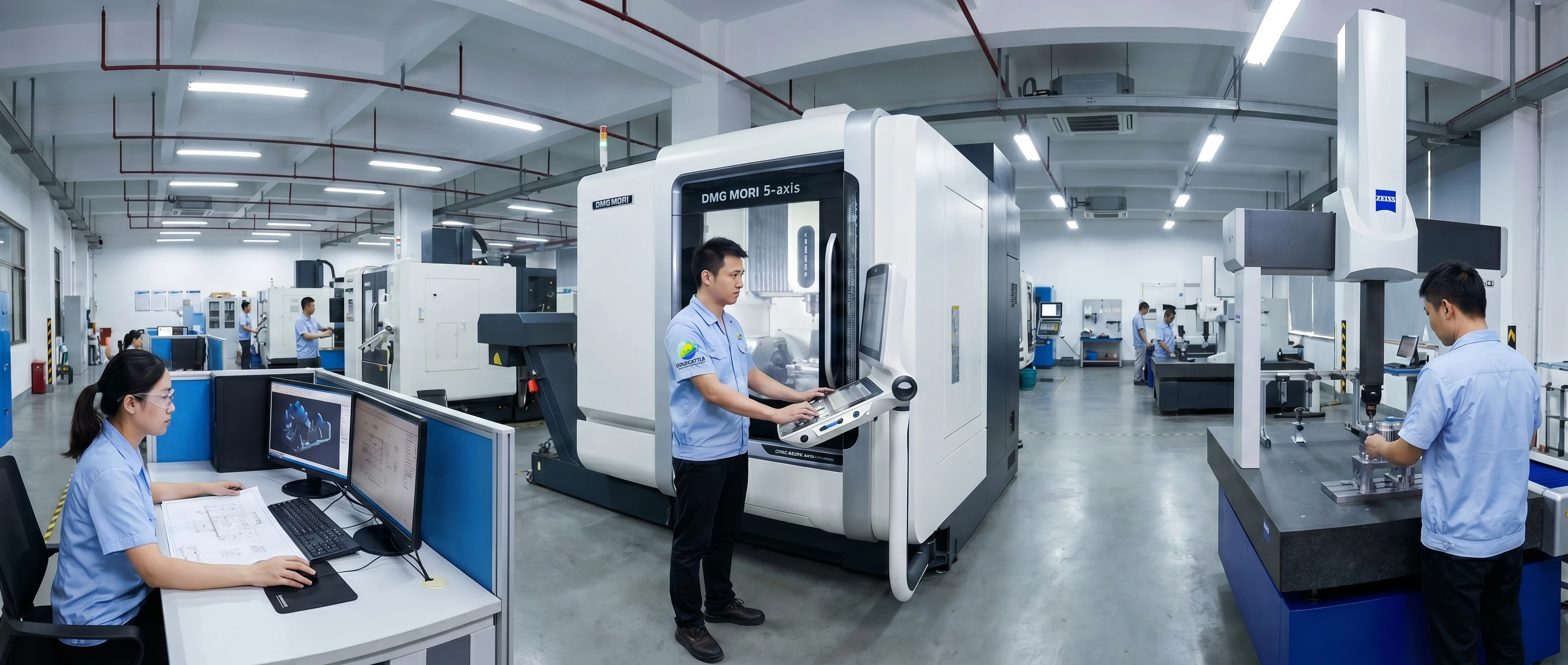
Xiamen Goldcattle walks buyers through every stage of CNC part production. This guide explains what happens at each step, what decisions affect cost, and how to prepare drawings that reduce machining expense by 20–40% through better DFM.
- CAD Design & DFM Review — 3D model creation + manufacturability analysis
- CAM Programming — Toolpath generation and machining strategy
- Material Preparation — Stock procurement and blank sizing
- Machine Setup — Workholding, tool loading and alignment
- CNC Machining — Roughing and finishing cuts per programmed path
- Quality Inspection — Dimensional verification and surface assessment
- Surface Finishing — Anodizing, plating, coating or polishing as specified
- Final Delivery — Packaging, documentation and shipment
CNC Milling Process Flow
Eight stages define the complete journey from drawing submission to finished parts in your hands. Each stage has decision points that directly affect unit cost, lead time and part quality.
Step 1: Design & Engineering Review
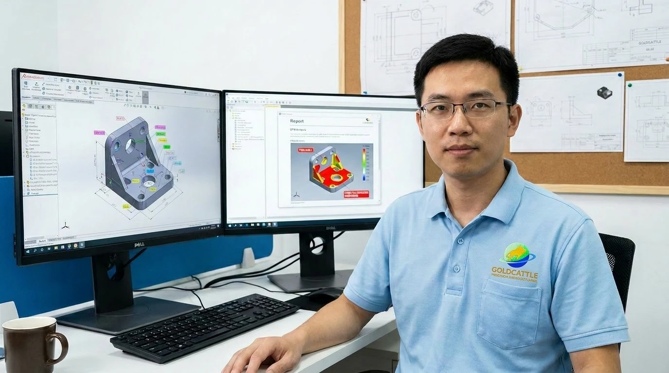
Every CNC project starts with a 3D CAD model — but not every model is ready for efficient machining. The DFM review identifies geometry that increases cost unnecessarily: overly thin walls, unreachable internal corners, over-toleranced non-critical dimensions, and features requiring special tooling.
What Happens at This Stage
| Activity | Purpose | Buyer Action | Impact on Cost |
|---|---|---|---|
| 3D Model Validation | Confirm geometry is complete and manufacturable | Provide STEP/DWG files with all features defined | Incomplete models add 1–2 days and revision cost |
| DFM Analysis | Identify features that increase machining difficulty | Review DFM report and approve recommended changes | Good DFM design reduces machining cost by 20–40% |
| Material Selection | Match alloy to application requirements and budget | Specify functional requirements (corrosion, strength, weight) | Material choice affects unit cost by 50–300% |
| Tolerance Assignment | Determine which features need tight vs standard tolerance | Mark critical dims on drawing; leave others at ±0.1mm default | Over-tolerancing adds 30–50% per feature |
Step 2: CAM Programming
CAM programming converts the 3D model into instructions the machine follows — toolpath coordinates, cutting speeds, feed rates and tool change sequences. Programming quality directly determines cycle time and surface finish quality.
What the Programmer Decides
| Decision | How It Affects Your Part | Typical Options |
|---|---|---|
| Toolpath Strategy | Determines cycle time and surface quality | Roughing: adaptive clearing — Finishing: contour/parallel |
| Tool Selection | Affects feature accuracy and corner radii | End mills: 2–12mm diameter — Ball mills: for 3D contours |
| Cutting Order | Impacts fixture complexity and part rigidity | Rough all pockets first → finish critical dims last |
| Feed Rate | Determines machining time per feature | Aluminum: fast feeds (5000+ mm/min) — Steel: moderate (2000–3000) |
Step 3: Material Preparation
Material selection is the single largest cost variable in CNC part production. Choosing the right alloy for your functional requirements — rather than defaulting to a “strongest” option — can reduce unit cost by 50% or more without compromising performance.
| Material | Common Application | Machinability | Relative Cost | Key Property |
|---|---|---|---|---|
| Aluminum 6061-T6 | General industry, brackets, housings | Excellent | Low | Good strength-to-weight ratio |
| Aluminum 7075-T6 | Aerospace, high-stress structures | Good | Moderate | Highest strength aluminum alloy |
| Stainless Steel 304 | Industrial equipment, marine hardware | Moderate | Moderate | Corrosion resistance |
| Brass C360 | Connectors, valves, decorative parts | Excellent | Low–Moderate | Free-machining, conductivity |
| Copper C110 | Electrical contacts, busbars | Good | Moderate | Electrical conductivity |
| POM (Delrin) | Gears, bearings, insulators | Very Good | Low | Low friction, dimensional stability |
Material Decision Guide
Choose Aluminum If You Need
Weight reduction in moving assemblies, corrosion resistance for outdoor hardware, anodized color finishes, fast machining for tight lead times, good thermal conductivity.
Choose Stainless Steel If You Need
Corrosion resistance in wet/saline environments, food-grade compliance (304), medical device components, high-temperature stability, weldability after machining.
Choose Brass / Copper If You Need
Electrical conductivity for contacts and terminals, free-machining for fast production, decorative finish for visible components, low friction for sliding assemblies.
Step 4: Machine Setup & Workholding
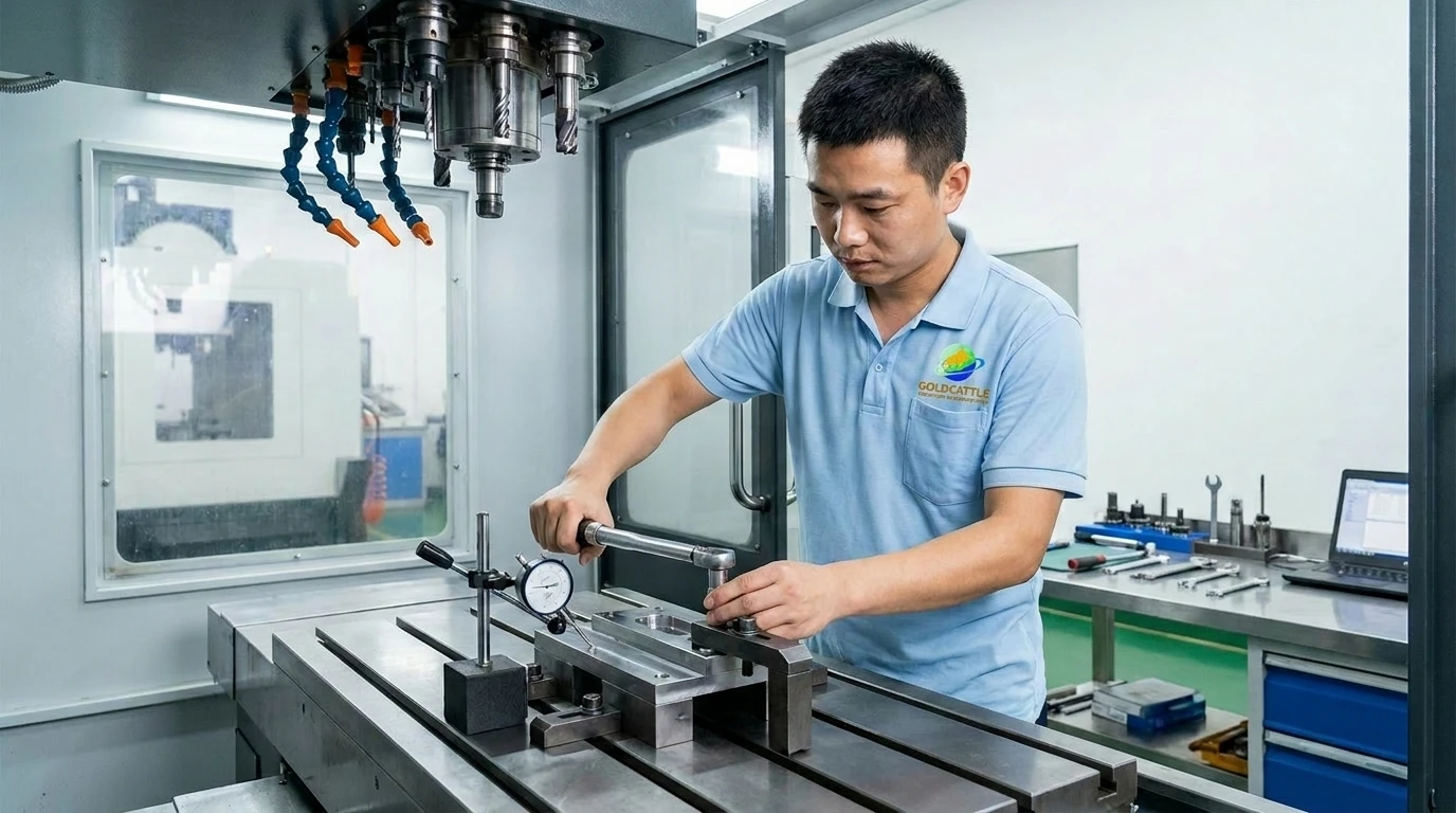
Setup determines part accuracy from the first cut. Fixture design, tool alignment and datum referencing all happen before machining begins — and setup complexity is a major cost driver, especially for low-volume orders where setup time amortizes over fewer pieces.
Setup Activities & Time Allocation
| Setup Activity | What It Achieves | Typical Duration | Cost Impact |
|---|---|---|---|
| Fixture Design | Secures part for all machining operations without repositioning errors | 30–120 min per setup | Custom fixtures add $50–200 per order |
| Tool Loading | Correct tool in correct magazine position — wrong tool ruins the part | 10–20 min | No extra cost — included in programming |
| Datum Alignment | Establishes X-Y-Z coordinate origin for all dimensions | 5–15 min | Poor datum choice adds rework risk |
| First Cut Verification | Confirms setup is correct before full-cycle run | 5–10 min | Catching setup errors early prevents scrap loss |
Step 5: CNC Machining
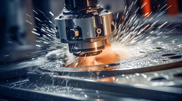
This is the cutting stage — where programmed toolpaths remove material to create the finished geometry. Roughing removes bulk material quickly; finishing achieves final dimensions and surface quality. Understanding this distinction helps buyers interpret lead-time estimates.
Machining Phases & Quality Impact
| Phase | Purpose | Surface Quality | % of Cycle Time |
|---|---|---|---|
| Roughing | Remove bulk material fast — 80% of stock removal happens here | Ra 3.2–6.3 μm | 40–60% of cycle time |
| Semi-Finishing | Bring features within 0.1–0.2mm of final dimension | Ra 1.6–3.2 μm | 15–25% of cycle time |
| Finishing | Achieve final tolerance and surface specification | Ra 0.4–1.6 μm (per requirement) | 20–30% of cycle time |
| Deburring | Remove sharp edges and machining burrs | Edge break 0.1–0.3mm | 5–10% of cycle time |
Step 6: Quality Inspection
Every part undergoes dimensional verification before shipment. First-article inspection validates the full production setup; in-process checks catch drift during batch runs; final inspection confirms every dimension meets specification.
| Inspection Type | Method | What Gets Checked | When |
|---|---|---|---|
| First Article | CMM full-dimension scan | All critical and general dims per drawing | First 1–3 pieces after setup |
| In-Process | Digital caliper + go/no-go gauge | Key dimensions every 10–20 pieces | During batch production |
| Final Inspection | CMM + visual + surface assessment | Full dimension report per shipment | Before packaging |
Lead Time & Cost Factors
Lead time spans every stage — not just cutting. Below is a typical timeline for standard-complexity custom parts. Complex 5-axis components or exotic materials may require additional time.
| Stage | Typical Duration | How to Reduce It |
|---|---|---|
| CAD / DFM Review | 1 Day | Provide complete STEP model — no missing features |
| CAM Programming | 1 Day (simple) – 3 Days (5-axis) | STEP file reduces interpretation time vs 2D drawing |
| Material Procurement | 0–3 Days | Specify standard alloys (6061, 304) — specialty stock takes longer |
| Machine Setup | 0.5 Day | Consolidate part numbers to share setup across batch |
| Machining | 1–3 Days (per complexity) | Simplify pocket geometry, reduce tolerance callouts |
| Surface Finishing | 1–3 Days (if required) | Anodizing and plating are outsourced — add 3–5 days |
| Inspection & Shipping | 1 Day | Clear tolerance spec reduces inspection time |
What Impacts Your Unit Cost
CNC Milling vs CNC Turning: Which Process Fits Your Part?
Both processes remove material with precision — but they produce fundamentally different geometry types. Milling creates flat surfaces, pockets and complex 3D features; turning produces cylindrical, conical and threaded profiles. Understanding which process fits your part reduces cost and improves quality.
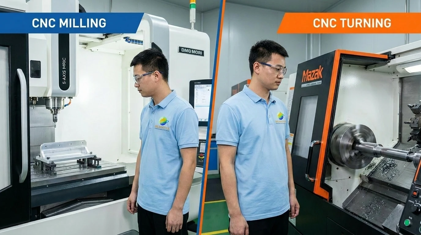
CNC Milling
Tool rotates; workpiece stationary
Flat surfaces, pockets, slots, 3D contours
3-axis standard; 5-axis for undercuts
CNC Turning
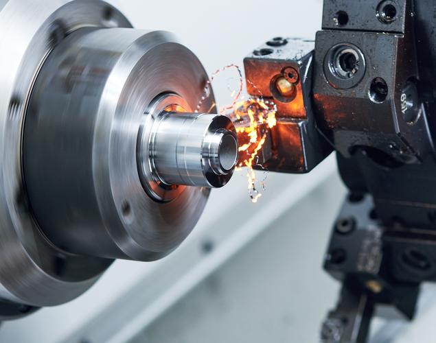
Workpiece rotates; tool stationary + linear motion
Shafts, bushings, threads, tapers, bored holes
2-axis standard; live tooling for cross-drilling
When Both Are Needed
Parts with round bodies + flat features (milled slots on a shaft, flat mounting faces on a bushing)
Mill-turn centers handle both in one setup
Real Buyer Cases: DFM Optimization Results
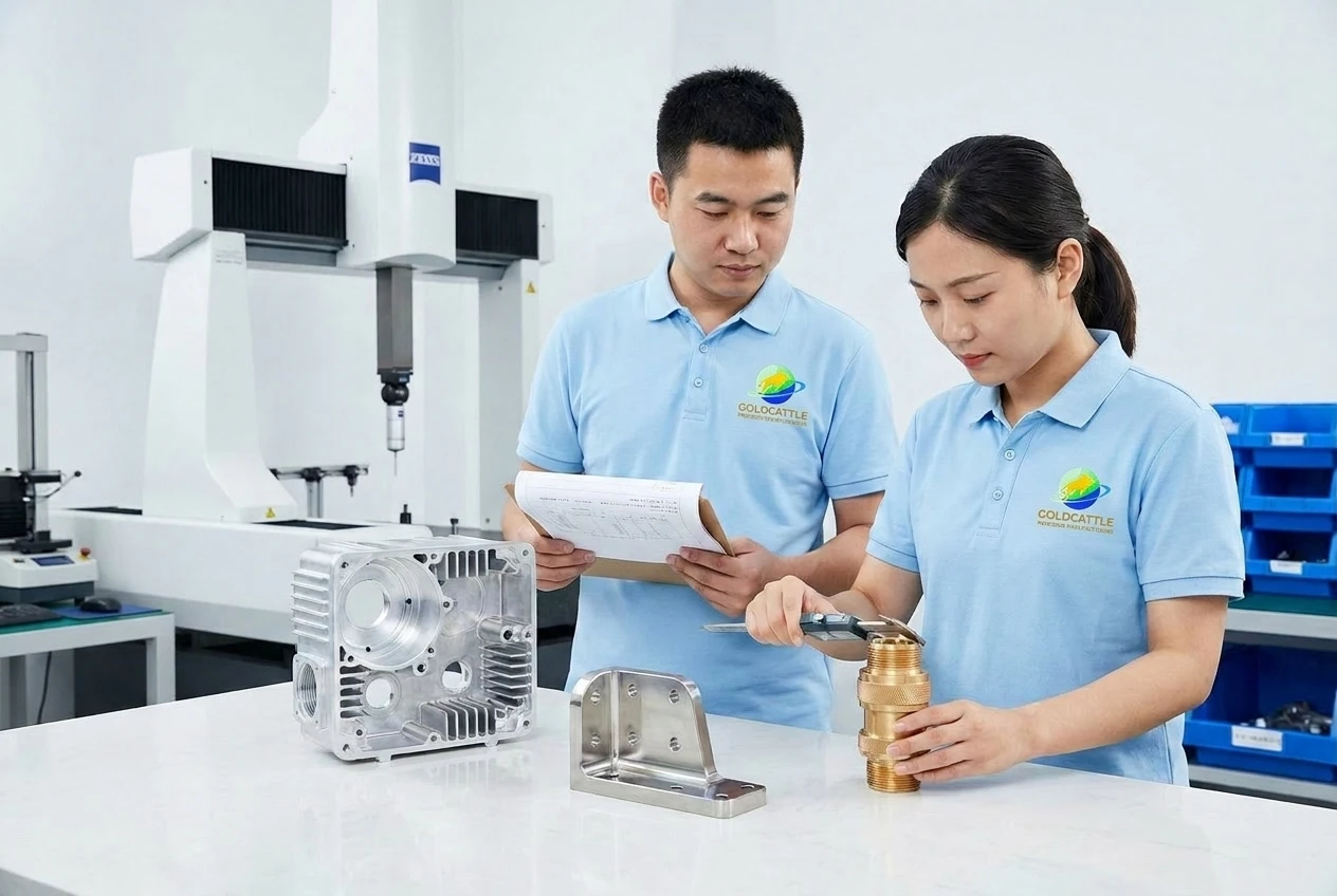
Case 1: Thin-Wall Aluminum Housing — 25% Cost Reduction
Case 2: Over-Toleranced Medical Bracket — 28% Cost Reduction
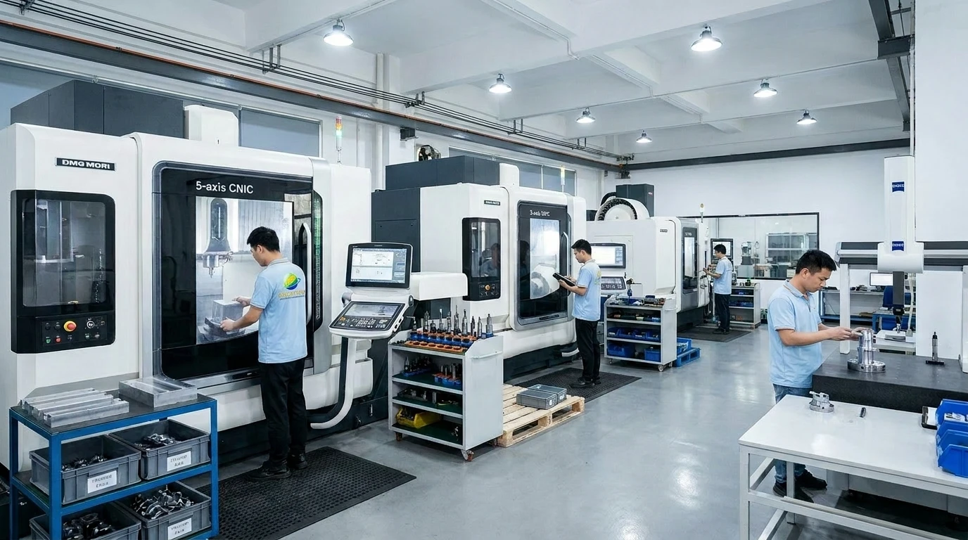
Xiamen Goldcattle — CNC Milling OEM Partner
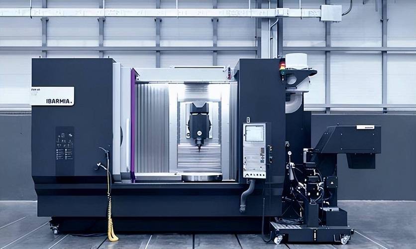
Goldcattle operates 5-axis and 3-axis CNC milling centers alongside turning, stamping, injection molding and sheet metal fabrication — meaning your milled components can move directly into secondary operations and assembly without changing suppliers or coordinating across vendors.
| Capability | Specification |
|---|---|
| CNC Milling | 3-axis and 5-axis, work envelope 600×400×300mm |
| Tolerance | ±0.01mm precision, ±0.1mm standard |
| Materials | Aluminum, Steel, Stainless, Brass, Copper, Titanium, POM, PEEK |
| Surface Finish | Ra 0.4–6.3 μm (as-machined to polished) |
| MOQ | 1 piece (prototype) to 10,000+ (production) |
| QC Standard | ISO 9001:2015 — FAI + SPC + Final COC |
Submit Your CNC Milling RFQ
Submit your drawing files and receive a comprehensive quotation — including DFM review, material recommendation and cost breakdown — within 24 hours.
Accepted File Formats
What You Receive
CNC Milling FAQ
CNC milling production involves 8 stages from design review to delivery. The three cost drivers are material choice (50–300% impact), tolerance level (+30–100% per feature), and order volume (setup amortization). DFM optimization can reduce machining cost by 20–40% by assigning tight tolerance only to functional dimensions and avoiding thin-wall geometry. Xiamen Goldcattle offers 3–5 axis CNC milling with ±0.01mm precision, ISO 9001:2015 QC, and 7–15 day standard lead time.
CNC Milling Specifications at a Glance
| Parameter | Specification |
|---|---|
| Process Steps | 8 stages: Design → CAM → Material → Setup → Machining → Inspection → Finishing → Delivery |
| Axis Capability | 3-axis (standard) / 5-axis (complex undercuts) |
| Tolerance Range | ±0.01mm (precision) / ±0.1mm (standard) |
| Surface Finish Range | Ra 0.4–6.3 μm |
| Materials | Aluminum, Steel, Stainless, Brass, Copper, Titanium, POM, PEEK |
| MOQ | 1–10,000+ pieces |
| Typical Lead Time | 7–15 days (standard) / 3–5 days (expedited) |
| QC Standard | ISO 9001:2015 — FAI + SPC + Final COC |