CNC drilling technology has been widely applied in modern manufacturing, especially showing great potential in micro – hole machining. The demand for micro – hole machining is becoming more and more common, covering various fields such as electronics, aerospace, and medical. This article will explore whether CNC drilling can achieve micro – hole machining and analyze its advantages and limitations.
I. Overview of CNC Drilling Technology
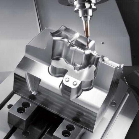
Computer Numerical Control (CNC) drilling is a technology that uses computer – controlled tools for hole machining. This technology enables high – precision and high – efficiency processing and is suitable for various materials. CNC drilling machines use computer programs to control the movement path and processing speed of the tool, ensuring high consistency and stability during the processing.
Basic Concepts of Drilling
Generally, drilling refers to a processing method of using a drill bit to machine holes on the surface of a product. Usually, when drilling a product on a drilling machine, the drill bit should complete two movements simultaneously:
- Main movement: The rotational movement of the drill bit around its axis (cutting movement).
- Secondary movement: The linear movement of the drill bit along the axis direction towards the workpiece (feeding movement).
During drilling, due to the shortcomings in the drill bit structure, marks will be left on the processed area of the product, affecting the machining quality of the workpiece. The machining accuracy is generally below IT10 level, and the surface roughness is about Ra12.5μm, belonging to rough machining.
II. The Drilling Super – Abilities of CNC
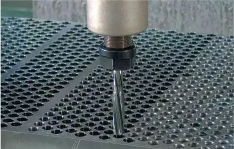
CNC machine tools are not only masters of engraving but also experts in drilling! Through program – controlled rotation and feeding of the drill bit, it can complete drilling operations with diameters ranging from 0.1mm to 50mm, with an accuracy of up to 0.01mm. It’s like using an intelligent robotic arm to hold an electric drill, capable of drilling vertically, at an angle, and even accurately opening holes on curved surfaces, which is difficult to achieve with ordinary bench drills.
Basic Principle of CNC Drilling Processing
CNC drilling processing controls the machine tool through a computer program to achieve automated processing of the workpiece. Compared with traditional manual processing, CNC processing has higher repeatability and accuracy. The drilling process generally includes steps such as fixture positioning, tool selection, and processing path planning, all of which are completed by the computer program, ensuring efficient and accurate processing.
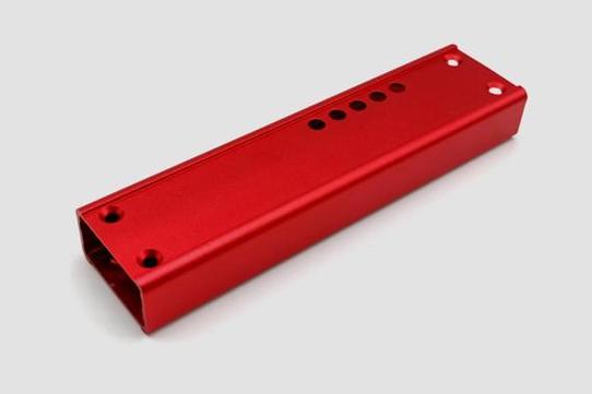
III. CNC Micro – Hole Machining
- High – Precision Machining: CNC drilling technology can achieve high – precision machining of micro – holes through an accurate control system. During the processing, according to the design requirements, the feed rate, rotational speed, and cutting depth of the tool can be flexibly adjusted to achieve the desired hole diameter and position accuracy.
- Diverse Material Processing: Xiamen Guansheng Precision Machinery Co., Ltd. was founded in 2015 and focuses on the design, production, and processing of various materials such as automated parts, hardware, and plastics. The company is equipped with multiple high – tech devices and can process a variety of materials, including metals, plastics, and composite materials, providing more options for micro – hole machining.
- Small – Batch Processing: CNC drilling machines have flexible processing capabilities and can perform single – piece or small – batch processing according to customer requirements. This means that when facing the demand for micro – hole machining, enterprises can respond quickly, adjust the production plan, and improve production efficiency.
IV. Three Ways of CNC Precision Hole Machining
- Reaming
- Reaming Process: First, drill a pre – hole, leaving a small amount of allowance, and then use a reamer to ream.
- This method is simple and relatively fast. However, the machine – adjuster next to it said, “What? Always using the reamer? Wuwu, you come and measure the tool run – out.” Then he went to complain to the supervisor. After listening, the supervisor said, “Oh, so you haven’t produced any work for a long time. It turns out you’ve been measuring the tool run – out back and forth. You’ve had a hard time.”
- Requirements: As long as the machine is in good condition, reaming is the preferred method. It can be used to process small holes, with diameters from 2mm to 10mm being more suitable. Of course, the specifications of reamers on the market are far more than that. It’s very easy to process holes like 4mm with a tolerance of ±0.02mm, 6mm with a tolerance of ±0.02mm, and 8mm with a tolerance of ±0.02mm. The allowance should not be too much, with a unilateral allowance of 0.1mm being the most perfect. For example, for a 4 – mm hole, first drill a 3.8 – mm hole. OK. The feed rate, rotational speed, and uniformity of the allowance of reaming will affect the size of the hole to a certain extent. In actual operation, appropriate adjustment is required. Both G01 and G81 can be used for reaming.
- Milling Holes (There are actually two types of milling holes)
- One is the light – edge form, and the other is the contour – parallel form
- This is easy to understand: First, use a tool for roughing, leaving the appropriate allowance, and then use a finishing tool. Isn’t it simple? For the light – edge form, it is also necessary to measure the tool run – out. If not, there may be a taper, where the upper part is qualified, but the lower part is defective. For the contour – parallel form, the tool run – out can be ignored if it is not too large. But if it rotates like a broom swinging, it won’t work. The contour – parallel form can solve the taper problem, but it increases the processing time and tool wear. It is more suitable for processing larger holes, with diameters from 3mm to 25mm being appropriate, and the depth needs to be determined according to the situation. When some machines process small holes, their movements seem to be shaking. In this case, the feed rate can only be appropriately reduced. These two types need to be used in conjunction with G41D – for easy adjustment.
- Boring
- Boring Process: First, perform roughing, leave the appropriate allowance, and then use a boring tool for finishing. Special tools, boring tools, are required here. If you don’t know what they look like, you can check my articles, where I have introduced them. Boring is suitable for processing relatively large holes, with diameters above 16mm. The largest I’ve seen can reach 398mm, and the depth can be ignored, depending on the situation of the tool. The holes processed by boring have guaranteed surface finish and perpendicularity, which can be controlled within about 0.01mm. It is relatively precise. Using a dial indicator in conjunction with adjusting the tool can achieve the processing accuracy. Here, G76 is recommended for processing.
V. Drilling Operation Process
- Marking Lines: Before drilling, first understand the requirements of the drawing. According to the basic standards of drilling, use tools to draw the center line of the hole position. The center line must be clear, accurate, and the thinner the better. After marking the lines, use a vernier caliper or steel ruler for measurement.
- Marking Inspection Squares or Inspection Circles: After marking the lines and passing the inspection, inspection squares or inspection circles centered on the hole center line should be marked as the inspection lines for trial – drilling, so as to check and correct the drilling position during drilling.
- Punching Center Pits: After marking the corresponding inspection squares or inspection circles, carefully punch the center pits. First, make a small dot, measure in different directions of the cross – center line several times to see if the punch mark is indeed on the intersection of the cross – center line. Then, punch the center pit firmly, roundly, and larger to ensure accurate tool positioning.
- Clamping: Wipe the machine tool table, fixture surface, and workpiece reference surface clean with a rag. Then clamp the workpiece, ensuring it is clamped flat, firmly, and is convenient for inspection and measurement at any time. Pay attention to the clamping method of the workpiece to prevent deformation due to clamping.
- Trial – Drilling: Before formal drilling, trial – drilling is necessary. Align the transverse edge of the drill bit with the center – pit of the hole and drill a shallow pit. Then visually check whether the position of the shallow pit is correct. Continuously correct the deviation to make the shallow pit coaxial with the inspection circle. If the deviation is small, while starting to drill, push the workpiece in the opposite direction of the deviation to gradually correct it.
- Drilling: In machining drilling, manual feeding is generally the main method. After the position accuracy of the trial – drilled hole meets the requirements, drilling can be carried out. When manually feeding, the feeding force should not cause the drill bit to bend to avoid the hole axis from being skewed.
VI. Why Choose CNC Drilling
- Precise Control: Automatically compensates for tool wear, and the depth error of each hole during batch processing is less than the thickness of a hair.
- Complex Processes: Completes drilling + chamfering + tapping in one go, reducing three process conversions.
- All – Material Compatibility: From aluminum alloy to titanium alloy, only the corresponding drill bit parameters need to be changed.
- Intelligent Error Prevention: Automatically alarms when encountering abnormal hardness to avoid drill – bit breakage accidents.