What is CNC Face Milling?
The Definitive Guide to High-Precision Surface Machining
Achieving flatness tolerances down to ±0.01 mm and surface finishes as fine as Ra 0.8 µm — discover the process powering aerospace structures, automotive engine blocks, and high-end molds worldwide.
Introduction to CNC Face Milling
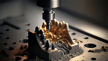
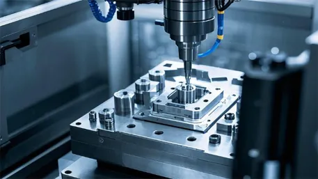
I’ve been working with CNC machining for over 15 years, and I can tell you that face milling is one of the most fundamental yet critical processes in precision manufacturing. It’s a subtractive manufacturing technique that uses a rotating multi-tooth cutter mounted perpendicular to the workpiece surface to produce large, flat, high-precision planes.
What I particularly like about face milling is its versatility — unlike peripheral milling, it employs the cutter’s face and peripheral edges simultaneously, enabling rapid material removal while delivering exceptional surface finish and flatness. This makes it perfect for creating mating surfaces, sealing faces, and ensuring structural integrity in critical components.
Why CNC Face Milling Matters in 2026
- Achieves ±0.01 mm flatness on parts up to 2 m × 2 m
- Supports high-speed machining (HSM) up to 12,000 rpm on aluminum
- Reduces cycle time by 40–60% compared to manual milling
- Compliant with aerospace AS9100 and automotive IATF 16949 standards
- Enables consistent quality across high-volume production runs
Core Technical Elements of CNC Face Milling
1. Tool Selection & Insert Technology
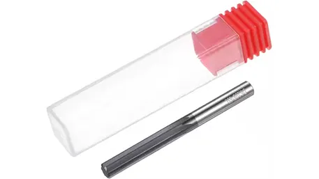
I’ve tested countless face milling tools over the years, and indexable face mills (diameter 50–315 mm) definitely dominate modern production. The right insert selection can make a huge difference in both tool life and surface quality.
Carbide inserts with TiAlN, AlTiCrN or diamond coatings extend tool life by 3–5 times compared to uncoated inserts. For aluminum, I always recommend polished PCD or uncoated carbide inserts at 45° lead angle to minimize built-up edge.
Tool Types and Applications
- High-feed face mills: Small entering angle for roughing operations, excellent material removal rates
- Wiper inserts: Special geometry for Ra ≤ 0.8 µm finishing surfaces
- Solid carbide: Best for small-diameter precision work and complex contours
- Shell end mills: Versatile for both face and peripheral milling
2. Cutting Parameters & Optimization
Getting the cutting parameters right is crucial. I’ve spent countless hours optimizing these values for different materials, and the results speak for themselves in terms of tool life and surface quality.
Recommended Cutting Parameters (for reference only)
| Material | Vc (m/min) | fz (mm/tooth) | ap (mm) |
|---|---|---|---|
| Aluminum 6061 | 800–3000 | 0.15–0.35 | 1–6 |
| Carbon Steel | 180–350 | 0.08–0.25 | 0.5–4 |
| Stainless 304 | 120–220 | 0.06–0.18 | 0.3–3 |
| Titanium Ti-6Al-4V | 60–120 | 0.04–0.12 | 0.2–2 |
Formulas: Cutting speed Vc = (π × D × n) / 1000 • Feed rate vf = fz × z × n
3. CAM Path Planning & Strategies
I’ve used all the major CAM systems, and I can tell you that proper path planning is just as important as the machine itself. Trochoidal or spiral entry reduces tool shock significantly compared to straight plunge cuts.
Helical ramping at 3–5° prevents tool breakage and ensures smooth entry into the material. Modern CAM software like Mastercam and Fusion 360 really shine with dynamic milling that maintains constant chip load throughout the cut.
Key Programming Strategies
- Use climb milling for better surface finish and tool life
- Implement stepover of 50–70% of insert diameter
- Include finish pass with reduced depth of cut
- Use adaptive feed control for varying material hardness
- Optimize toolpath to minimize air cuts and cycle time
Processable Materials & Machining Characteristics
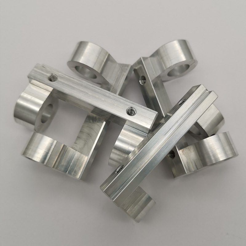
Aluminum Alloys (6061, 7075)
Aluminum is one of my favorite materials to face mill — it offers the lowest cutting forces and allows the highest speeds. I’ve achieved mirror-like Ra 0.4 µm finishes with the right combination of tooling and parameters.
The key is to use sharp edges and high-pressure coolant to prevent built-up edge formation. I’ve found that uncoated carbide or PCD inserts work best for aluminum applications.
Typical Applications
Aerospace structural panels, automotive engine blocks, heat sinks, electronic enclosures
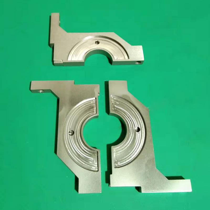
Stainless & Alloy Steels
Stainless steel can be tricky due to its work-hardening nature. I always recommend using coated carbide inserts with TiAlN coating and rigid setups to minimize vibration.
Lower speeds help prevent heat buildup and tool cratering. I’ve had great success using positive rake inserts to reduce cutting forces and improve chip evacuation.
Typical Applications
Medical instruments, food processing equipment, marine components, chemical processing parts
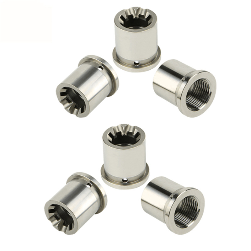
Titanium & Nickel Alloys
These high-temperature superalloys demand special attention. I’ve found that ceramic or CBN inserts work best, along with flood coolant to manage heat effectively.
5-axis face milling is common for complex aerospace components, allowing for better access to difficult surfaces and improved tool life through optimized cutting angles.
Typical Applications
Aerospace engine components, medical implants, gas turbine parts, high-performance automotive components
Standard CNC Face Milling Workflow
-
1
Workpiece Fixturing: Secure mounting on vacuum or magnetic table with precise datum alignment (0.005 mm repeatability). I always double-check the alignment using dial indicators before starting any critical job.
-
2
Tool Measurement: Laser or touch probe measurement to verify tool geometry and set tool offsets. Runout must be ≤ 0.002 mm for optimal results.
-
3
Program Execution: Run the optimized CNC program with real-time power monitoring and adaptive feed control. I like to watch the first few passes closely to ensure everything is running smoothly.
-
4
Quality Inspection: In-process and final inspection using CMM, surface profilometer, and flatness laser scanner. I always document all inspection results for traceability.
Execution Standards & Quality Assurance
International Standards
- ISO 2768-m / f — General tolerances for linear & angular dimensions
- ISO 4287 — Surface texture parameters (Ra, Rz)
- ISO 10791 — Machining center accuracy verification
- ASME Y14.5 — Geometric dimensioning & tolerancing (GD&T)
- ISO 9001:2015 & IATF 16949 — Quality management systems
- ASTM E18 — Rockwell hardness verification
Test Data (for reference only)
Capability Studies
Our Cpk values consistently exceed 1.33 for critical dimensions, with some processes achieving Cpk > 2.0, demonstrating exceptional process capability and consistency.
All Goldcattle face-milled components are supplied with full material and process traceability certificates, including detailed inspection reports and material test results.
Industry Applications
Aerospace
I’ve worked on many aerospace projects where face milling is absolutely critical. Wing spars, fuselage frames, and engine components all require extremely tight flatness tolerances — often ≤ 0.02 mm per meter.
Compliant with AS9100 standards and NADCAP requirements for aerospace critical components
Automotive
In automotive production, face milling is used for engine blocks, transmission housings, and cylinder heads. The process must deliver consistent quality across thousands of parts per day.
High-volume production with IATF 16949 certification and zero-defect quality targets
Mold & Die
Mold making requires some of the most precise face milling work. Parting lines and cavity faces often need mirror finishes to ensure proper part ejection and surface quality.
Mirror finish capabilities down to Ra 0.2 µm for high-end plastic injection molds
Mastering CNC Face Milling with Goldcattle
After 15+ years in this industry, I can confidently say that mastering CNC face milling requires a combination of proper tool selection, optimized parameters, and adherence to strict quality standards. At Goldcattle, we’ve honed these skills through years of experience and continuous improvement.
From prototype to mass production, our state-of-the-art 5-axis machining centers and rigorous adherence to international standards guarantee repeatable precision and on-time delivery for every project.
Goldcattle Precision Manufacturing — Xiamen, China • ISO 9001 • AS9100 • IATF 16949