Answer
CNC modeling refers to the process of creating a 3D digital model of a part through Computer – Aided Design (CAD) software and converting the model into Numerical Control (NC) code (such as G – code) using Computer – Aided Manufacturing (CAM) software. This process requires precise setting of materials, tool paths, machining parameters, etc. Finally, it drives the CNC machine tool to automatically complete material cutting, which is a core link connecting product design and actual processing.
Explanation (A vivid and simple metaphor)
CNC modeling is like writing a “construction manual” for a machine tool:
CAD modeling: It’s like building a “digital part” with virtual building blocks. Designers draw the three – dimensional appearance of the part on the computer (such as the curved surface of a mobile phone case or the tooth pattern of a gear), just like an architect drawing a blueprint.
CAM programming: It is to translate the blueprint into “construction steps” that the machine tool can “understand”. For example, “mill the top plane first, then drill 5 holes with a diameter of 2mm, and finally round the corners”. Each action is converted into precise numerical control codes, just like giving “robot instructions” to the machine tool.
Ultimately, the machine tool is like a “mechanical worker” holding the manual, processing a raw material into the designed part step by step.
Problem Expansion
Core Process and Key Technologies
CAD Design Phase
Commonly used software: SolidWorks (suitable for mechanical parts), UG/NX (for complex surfaces), AutoCAD (for 2D – to – 3D conversion).
Key points: Ensure that the model’s dimensional tolerances (such as ±0.01mm) and surface roughness (such as Ra 0.8μm) meet the processing requirements, and avoid problems like “good – looking design but unprocessable” (such as overly narrow grooves).
CAM Programming Phase
Core tasks:
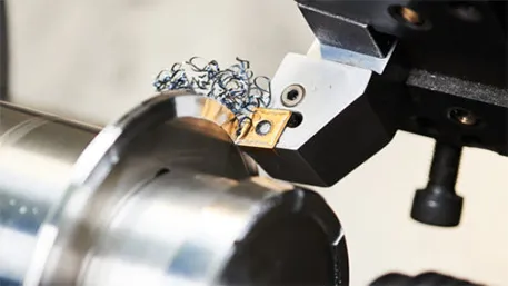
Tool selection: Select tools according to the hardness of the material (for example, use carbide tools for aluminum alloys and ceramic tools for titanium alloys);
Path planning: Design the “most labor – saving” cutting route to reduce idle cutting and tool wear (for example, use spiral plunge instead of vertical hard cutting when milling a plane);
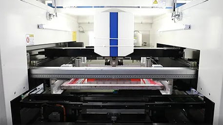
Simulation verification: Simulate the machining process through software to detect collision or over – cutting problems in advance and avoid damage to the machine tool.
Differences from 3D Printing Modeling
CNC modeling: Based on a “subtractive thinking”, it is necessary to reserve the amount of material to be removed, and focus on the accessibility of the tool (for example, when machining deep holes, consider the length of the tool shank);
3D printing modeling: Based on an “additive thinking”, pay more attention to the design of hollow structures and supports in the model (for example, add support columns for hollow parts).
Application Scenarios and Industry Value
Product R & D: Automobile manufacturers use CNC modeling to process engine prototypes to verify assembly accuracy;
Mold Manufacturing: Injection mold manufacturers engrave the cavity through CNC modeling to ensure smooth demolding of plastic parts;
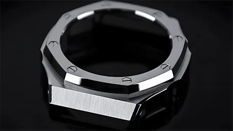
Precision Part Customization: In the medical field, CNC modeling is used to make personalized artificial joints that match the curvature of the patient’s bones (with an error < 0.1mm).
The accuracy of CNC modeling directly determines the quality of parts. For example, the CNC modeling of the iPhone’s mid – frame needs to be accurate to 0.005mm to meet the technological requirement of “seamlessly fitting the screen”. Therefore, it is not only a technical process but also the “digital soul” of industrial manufacturing.