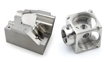
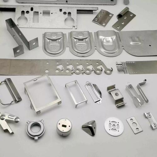
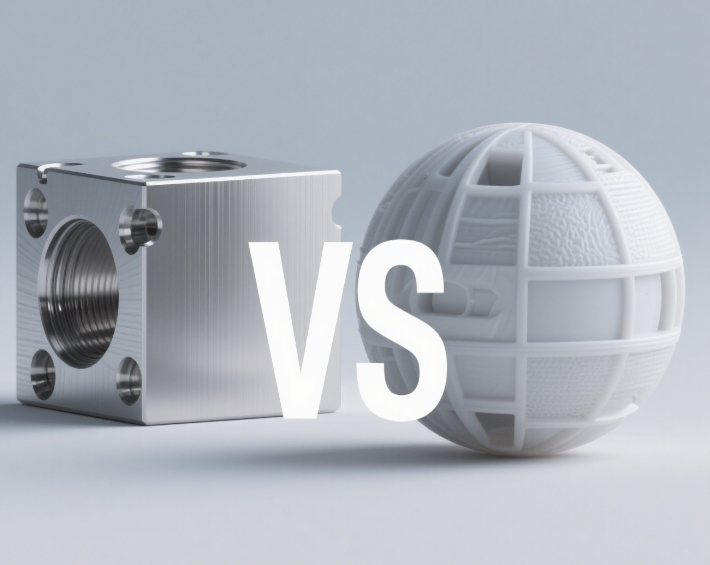
Precision CNC Parts Machining Services
Custom Metal & Plastic Components — From Prototype to Production
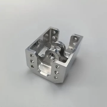
Engineered components machined to your specifications. Fast lead times, tight tolerances, and full material traceability as standard.
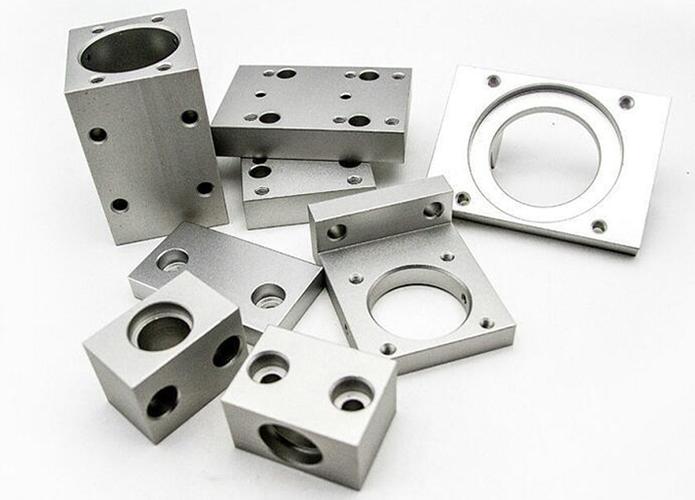
- 3-Axis to 5-Axis CNC Milling & Turning — complex contoured parts, prismatic components, and turned work from a single set-up.
- Tolerances as Tight as ±0.005 mm — suitable for precision mating parts, medical devices, and aerospace-grade components.
- Wide Material Range — aluminum alloys, stainless steels, titanium, brass, copper, and engineering plastics (PEEK, Delrin, Nylon).
- Flexible Production Volume — single-piece prototypes through to 100,000+ unit production runs. MOQ 1 pc.
- Full Traceability & Inspection — material certs, CMM dimensional reports, surface finish verification, and PPAP/APQP support available.
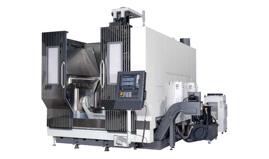
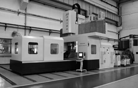
Manufacturing Capabilities
| Capability | Specification |
|---|---|
| CNC Milling | Up to 5-axis simultaneous |
| CNC Turning | Multi-axis with live tooling |
| Maximum Part Size (Milling) | 1500 × 800 × 600 mm |
| Maximum Turning Diameter | 400 mm |
| Standard Tolerance | ±0.01 mm |
| Precision Tolerance (by geometry) | ±0.005 mm |
| Surface Roughness (Ra) | 0.8 µm standard; 0.4 µm achievable |
| Minimum Wall Thickness | 0.5 mm (aluminum); 0.8 mm (stainless steel) |
| Materials | Aluminum (6061/7075/5083), Stainless (304/316/303), Titanium (Grade 2/5), Mild Steel, Tool Steel, Brass, Copper, PEEK, Delrin (POM), Nylon, PTFE, Polycarbonate |
| Surface Finishes | Anodizing, Hardcoat Anodizing, Passivation, Electropolishing, Zinc/Nickel Plating, Powder Coating, Bead Blasting, Chemical Film, Painting |
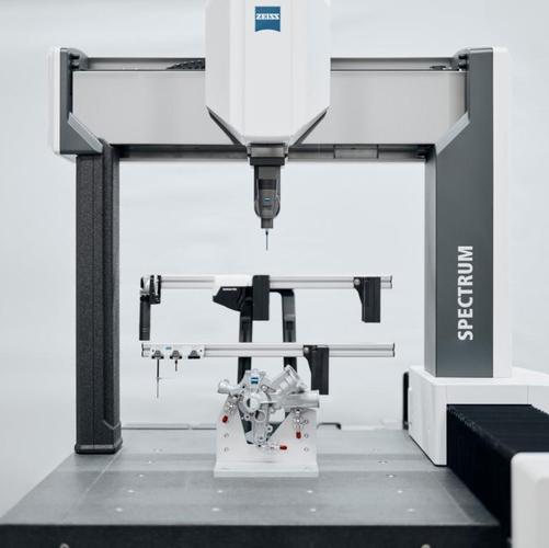
| Inspection Equipment | CMM (Coordinate Measuring Machine), Optical Comparator, Mitutoyo instruments, Surface Roughness Tester, Thread Gauges, Hardness Tester |
| Quality System | ISO 9001-certified production environment |
| MOQ | 1 piece (prototype); flexible production volumes |
| Lead Time (Prototype) | 3–7 working days |
| Lead Time (Production) | 7–20 working days (volume-dependent) |
| File Formats Accepted | STEP, IGES, SolidWorks, Parasolid, DWG, PDF, STL |
Material Selection Guide
Material choice affects machinability, mechanical properties, corrosion resistance, and finished part cost. The table below summarises the materials we process most frequently, with guidance on where each excels.
| Material | Key Properties | Best For | Machinability Notes | Typical Applications |
|---|---|---|---|---|
| Aluminum 6061-T6 | Good strength-to-weight ratio, excellent machinability, corrosion resistant | General-purpose structural parts, housings, brackets | Chips easily, minimal tool wear | Electronics enclosures, automotive components, industrial fixtures |
| Aluminum 7075-T6 | Very high strength, comparable to mild steel | High-stress, lightweight structural components | Requires rigid fixturing; use polished sharp tools to manage chip welding | Aerospace brackets, drone chassis, high-end bicycle parts |
| Stainless Steel 304/304L | Excellent corrosion resistance, good toughness | Food processing, medical, marine | Work-hardens; use positive rake tools and moderate speeds | Surgical instruments, pump housings, chemical handling equipment |
| Stainless Steel 316/316L | Superior pitting and crevice corrosion resistance | Marine, pharmaceutical, harsh chemical environments | Similar to 304 but slightly tougher to machine | Marine fittings, pharmaceutical process components |
| Titanium Grade 5 (Ti6Al4V) | Highest strength-to-weight ratio, biocompatible | Aerospace, medical implants | Low thermal conductivity; requires flood coolant and sharp tools | Orthopedic implants, aerospace fasteners, high-performance automotive |
| Brass (C360) | Excellent machinability (100% rating), good electrical conductivity | Electrical connectors, fluid fittings | Free-cutting; extremely low tool wear | Sensor housings, pneumatic connectors, decorative parts |
| PEEK (Polyether Ether Ketone) | High chemical resistance, steam sterilizable, high-temperature stability (260°C) | Medical, semiconductor, oil & gas | Maintains dimensional stability; requires carbide tooling and cooling | Surgical instrument handles, semiconductor wafer guides, seal rings |
| Delrin (POM) | High stiffness, low friction, excellent dimensional stability | Gears, bearings, structural plastic parts | Machines cleanly; avoid coolant on some grades | Conveyor components, snap-fit enclosures, precision spacers |
Our engineering team will recommend the optimal material for your application during the DFM phase — balancing cost, performance, and lead time.
Surface Finishing Capabilities
Surface finishes enhance functional performance, corrosion resistance, and cosmetic appearance. We combine in-house and qualified partner facilities to offer a complete finishing service.
| Finish | Substrate | Purpose | Typical Thickness / Specifications | Notes |
|---|---|---|---|---|
| Anodizing (Type II) | Aluminum | Corrosion resistance, colouring, light wear protection | 5–25 µm | Available in clear, black, blue, red, gold, etc. |
| Hardcoat Anodizing (Type III) | Aluminum | High wear resistance, extreme durability | 25–100 µm | Suitable for sliding surfaces, military/aerospace |
| Passivation | Stainless Steel | Restore corrosion resistance by removing free iron from surface | Per ASTM A967 | Standard for all stainless parts unless otherwise specified |
| Electropolishing | Stainless Steel | Ultra-clean, smooth surface (Ra <0.5 µm achievable) | Removes 20–30 µm material | Medical, pharmaceutical, semiconductor |
| Zinc Plating / Nickel Plating | Steel | Corrosion protection, wear resistance | 5–25 µm (Zn); 10–50 µm (Ni) | Cost-effective for mild steel components |
| Powder Coating | Aluminum, Steel | Impact-resistant durable finish, wide colour range | 50–120 µm | Available in gloss, matte, textured, RAL colours |
| Bead Blasting | All metals | Uniform matte texture, surface preparation | N/A (surface texture) | Often applied before anodizing or painting |
| Chemical Film (Alodine) | Aluminum | Corrosion protection, electrical conductivity | 0.5–4 µm | Used in electronics for grounding continuity |
| Black Oxide | Steel, Stainless | Mild corrosion resistance, non-reflective black surface | <1 µm | Dimensional stability — negligible thickness added |
We provide Certificate of Conformance (CoC) and applicable process certifications for all finishing operations. For critical applications requiring certified plating to MIL or AMS specs, contact our team.
Industry-Specific CNC Machining Solutions
Different industries demand different levels of precision, documentation, and process control. Our operations are structured to meet these diverse requirements.
| Industry | Typical CNC Machined Parts | Key Requirements We Fulfil |
|---|---|---|
| Aerospace | Structural brackets, avionics housings, actuator components | AS9100-aligned processes (ISO 9001), ±0.005mm tolerances, FAI (First Article Inspection) reports, full material traceability |
| Medical & Surgical | Orthopedic cutting guides, instrument handles, endoscope components | Biocompatible materials, surface finish Ra ≤0.4µm, cleanroom-ready packaging, validated passivation/electropolishing |
| Automotive & EV | Engine components, battery enclosure parts, sensor mounts | PPAP Level 3 documentation, high-volume capacity, functional coating systems, serial traceability |
| Electronics & Semicon | Heat sinks, RF housings, connector bodies, wafer handling parts | Tight flatness, specific conductivity (chemical film), burr-free edges, cleanroom processing |
| Industrial Automation | End-of-arm tooling, sensor brackets, precision shafts, gearbox components | Wear-resistant materials (tool steel, titanium), heat treatment integration, balanced rotating parts |
| Consumer Products | Bespoke enclosures, mechanical substructures, mounting plates | Cosmetic surface finishes, low MOQ for market testing, fast turnaround for design iterations |
| Oil & Gas | Downhole tool components, valve bodies, instrumentation housings | Corrosion-resistant alloys (316, Inconel upon request), NDT (Non-Destructive Testing) options, high-pressure compatibility |
When you submit a drawing, our engineers identify the critical-to-quality features and propose a manufacturing control plan aligned with your industry’s expectations.
Engineering Challenges & Proven Solutions
CNC machining complex parts presents recurring technical challenges. The table below documents problems we solve daily — knowledge that translates directly into better parts for our clients.
| Machining Challenge | Why It Occurs | Our Proven Mitigation |
|---|---|---|
| Thin-wall deflection (≤1.0 mm) | Cutting forces cause vibration & dimensional deviation | Use of vacuum fixtures, symmetric roughing strategy, low radial engagement toolpaths, stress-relief cycles between ops |
| Chatter / surface waviness | Resonant vibration due to tool overhang or insufficient rigidity | Optimized tool stick-out ratio (<4:1), tuned cutting parameters (spindle speed matching), moulded carbide anti-vibration bars |
| Work hardening (stainless steel) | Plastic deformation during cutting increases hardness locally | Employ positive rake angles, maintain continuous feed to avoid rubbing, use coated carbide tools |
| Internal corner radii too small | Designer spec < tool radius; forces use of micro tools or EDM | DFM feedback: increase internal radius to ≥ R1.0mm; where unavoidable, 5-axis or sinker EDM applied |
| Deep cavity chip evacuation | Chips packing in cavity causes tool breakage and surface scratching | Through-spindle coolant, peck drilling cycles, helical toolpaths to lift chips out; high-pressure flood coolant |
| Thread strength in aluminium | Soft material prone to stripping under load | Use helical coil inserts (Helicoil) for high-load threads; design thread engagement ≥ 2× diameter strength length |
| Titanium heat build-up | Low thermal conductivity concentrates heat at cutting edge | High-pressure coolant delivery (70+ bar), TiAlN-coated tools, reduced cutting speeds, climb milling |
| Burr formation on edges | Tool exit or material ductility | Secondary vibratory deburring, thermal deburring for internal passages, sharp tooling with programmed tool changes |
These engineering solutions are embedded in our process planning before the first chip is cut.
Design for Manufacturing (DFM) Guidelines
Optimising your part design for CNC machining reduces cost, shortens lead times, and improves quality. Below are the key geometry recommendations our engineering team applies during DFM reviews.
| Design Feature | Recommended Practice | Why |
|---|---|---|
| Wall thickness | ≥0.8 mm for metals, ≥1.0 mm for plastics | Prevents deflection and vibration during cutting |
| Internal corner radii | ≥R1.0 mm (or 1/3 × cavity depth) | Allows standard end mill access; eliminates expensive EDM |
| Hole depth-to-diameter ratio | ≤10:1 for standard drilling | Deeper holes increase risk of drill wander and breakage |
| Thread design | Max thread depth = 2.5× diameter in blind holes | Enough strength; deeper adds cost without significant strength gain |
| Tolerance assignment | Apply tight tolerances only to functional interfaces | Over-tolerancing multiplies inspection and machining time |
| Undercuts | Use standard dovetail or T-slot cutter dimensions where possible | Custom tooling increases cost and lead time |
| Text engravings | Minimum line width 0.5 mm, depth 0.3 mm | Ensures legibility; use ball end mills for smooth bottoms |
| Edge breaks | Specify 0.1–0.5 mm x 45° chamfer or R0.1–0.3 mm radius | Deburrs edges and improves safety; no ambiguity in drawing |
Submit your STEP or IGES file for a free DFM analysis. Our engineers will flag potential machining issues and suggest modifications that reduce cost without compromising function.
Case Study — Precision Surgical Instrument Handle
Project Context
A UK-based medical device startup needed 200 precision-machined handles for a new laparoscopic surgical tool. Critical requirements: mirror-smooth surface finish for sterilisation, ergonomic contour, and integration of a complex internal lumen.
| Material | 316L Stainless Steel (electropolished) |
| Machining Process | 5-axis CNC milling + CNC turning |
| Key Tolerance | ±0.01 mm on mating interface; outer surface profile tolerance 0.05 mm |
| Surface Requirement | Ra ≤0.2 µm after electropolish |
| Challenge | Maintaining consistent wall thickness (1.2 mm) along the curved, ergonomic grip without distortion |
| Solution | 5-axis simultaneous machining with dynamic tool engagement; purpose-built fixture nesting the contoured blank; intermediate stress-relief run between roughing and finishing |
| Inspection | 100% CMM dimensional report, borescope inspection of internal lumen, surface roughness trace, material cert provided |
| Lead Time | 15 working days from design freeze to delivery |
Outcome
All 200 units passed first-article inspection zero rejects. The client has since placed three subsequent orders and moved the product into full clinical trial production. This case demonstrates our ability to handle surgically clean, tight-tolerance, aesthetic CNC components.
⚠️ Replace with a real Goldcattle case study including actual images, part numbers, or customer testimonials (with permission). Authentic data significantly strengthens B2B buyer confidence.
Frequently Asked Questions (FAQs)
1. What tolerances can Goldcattle hold on CNC machined parts?
Standard tolerance is ±0.01 mm. We can hold ±0.005 mm on critical features depending on part geometry and material. A full CMM report is provided with every production batch.
2. Do you do 5-axis CNC machining?
Yes. We run 5-axis simultaneous machining centres capable of producing complex sculpted surfaces, compound angles, and deep cavities in a single setup — reducing lead time and improving accuracy.
3. What file formats do you accept for quoting?
STEP (.stp) and IGES (.igs) are preferred. We also accept SolidWorks, Parasolid, DWG, PDF, and STL. If you only have a sketch or idea, our engineering team can help create a 3D model.
4. Can you provide material certifications?
Yes. Material test reports (mill certs) to EN 10204 3.1 or equivalent are standard on all production orders. Full material traceability is maintained.
5. What is your minimum order quantity (MOQ)?
1 piece for prototypes. We support low-volume production and scale seamlessly to mass production runs of 100,000+ units.
6. How long does a CNC machining quote take?
We respond within 24 hours (often same day) with a detailed quotation once we receive your 3D files and requirements.
7. What surface finishes do you offer?
We offer anodizing (Type II and III), passivation, electropolishing, zinc/nickel plating, powder coating, bead blasting, chemical film, and black oxide. All finishes are applied to spec with certifications.
8. Can you machine plastics as well as metals?
Absolutely. We machine PEEK, Delrin (POM), Nylon, PTFE, polycarbonate, and other engineered plastics. These require different tooling and parameters, which we dial in per job.
9. Do you support low-volume production or just mass production?
We actively support low-volume production (1–500 parts). Our flexible setup allows economic machining of small batches for market testing, spares, or limited-edition products.
10. What quality inspection process is used?
Every batch undergoes CMM dimensional inspection, visual inspection, and thread/hardness checks as applicable. First Article Inspection (FAI) reports, PPAP, and capability studies are available for critical applications.
11. Can you sign NDAs (Non-Disclosure Agreements)?
Yes. We regularly sign NDAs to protect client IP. This can be executed before any technical discussion begins.
12. How do you handle international shipping?
We ship globally via DHL, FedEx, UPS for prototypes, and consolidated air/sea freight for production volumes. We offer EXW, FOB, DAP terms as preferred.
13. Can you handle extra-large parts?
Our maximum machining envelope is 1500 × 800 × 600 mm. For larger parts, we have partner facilities; please send details for feasibility review.
14. Do you offer assembly or sub-assembly services?
Yes. We provide component assembly, bearing insertion, thread insert installation, labelling, and custom packaging according to your specifications.
15. What is your approach to preventing deformation when machining thin-walled parts?
We employ vacuum workholding, balanced roughing/finishing sequences with intermediate stress relief, optimised tool engagement angles, and adaptive clearing strategies to minimise cutter load on thin sections.
16. Can you match a specific RAL or Pantone colour for powder coating?
Yes. Powder coating can be precisely matched to RAL and Pantone colours. Anodizing dye colours are more limited but we can match closely; samples are provided for approval before production.
17. Are you certified?
Our facility operates under an ISO 9001-certified quality management system. Specific customer audits are welcomed.
Request a Quote — How to Start
Start your CNC machined part project now.
Send the following to [your engineering email] or upload via our secure form:
- ✓
3D CAD files — STEP or IGES preferred, PDF/STL accepted - ✓
Material specification — or describe your application; we’ll recommend - ✓
Quantity — prototype, low volume, or mass production - ✓
Surface finish — cosmetic requirement or functional spec - ✓
Critical tolerances & features — highlight functional interfaces - ✓
Application context — helps us refine DFM suggestions
What to expect:
- DFM Feedback (within 24h) — Our engineers review manufacturability and suggest minor design tweaks that lower cost or improve quality.
- Transparent Quote — Detailed pricing with lead time. No hidden costs.
- First-Article Approval — Machined sample shipped for your physical evaluation and sign-off.
- Production & Full Inspection — Every production batch comes with a complete inspection report.
- Global Delivery — Packaged securely, documents included.
No CAD file? Send your concept sketch or reference photos. Our team will build a 3D model and provide a quote based on the generated geometry.