In die casting, the “mold” is officially called a die—a precision-engineered, reusable metal tool that shapes molten metal into the desired part geometry. Unlike single-use molds (e.g., sand casting molds), die casting dies are designed for high-volume production, withstanding thousands to millions of heating/cooling and pressure cycles.
Its primary role is to:
- Hold molten metal (zinc, aluminum, magnesium) under high pressure (1,000–15,000 psi).
- Cool the metal quickly into a solid part that matches the die’s internal cavity.
- Allow easy ejection of the finished part for repeatable production.
Below, we’ll break down the die’s structure, types, materials, manufacturing process, and key factors that impact its performance—critical knowledge for anyone designing or sourcing die cast parts.
Step 1: Core Structure of a Die Cast Mold (Key Components)
A die casting die is a two-part assembly (at minimum) with specialized components to ensure metal flows smoothly, cools evenly, and parts eject without damage. Here’s a breakdown of its essential parts:
| Component | Location | Function |
|---|---|---|
| 1. Fixed Die (Cover Die) | Attached to the die casting machine’s stationary platen | Contains the sprue (main channel that feeds molten metal into the die) and aligns with the machine’s injection system. It stays stationary during production. |
| 2. Moving Die (Ejector Die) | Attached to the machine’s movable platen | Holds the cavity (the hollow space that defines the part’s shape) and the ejection system (pins, sleeves, or plates that push the solid part out after cooling). It opens/closes with the machine. |
| 3. Cavity | Inside fixed/moving die (matches part shape) | The “negative” of the final part—molten metal fills this space to form the part. Cavities can be single (one part per cycle) or multiple (multiple parts per cycle). |
| 4. Gating System | Connects sprue to cavity (channels) | Controls molten metal flow: – Runner: Distributes metal from sprue to cavity. – Gate: Small opening that feeds metal into the cavity (controls flow speed/pressure). – Overflows: Extra spaces that catch impurities or air before they enter the cavity. |
| 5. Venting System | Along cavity edges (tiny channels: 0.1–0.3mm wide) | Releases trapped air and gas from the cavity during injection—prevents porosity (air bubbles) in the final part. Poor venting is a top cause of part defects. |
| 6. Ejection System | Inside moving die (pins, plates, sleeves) | Pushes the solid part out of the cavity once cooled. Ejector pins leave small “pin marks” (usually hidden on non-visible part surfaces). |
| 7. Cooling System | Embedded in die (water/oil channels) | Cools the die and molten metal quickly (critical for cycle time and part strength). Faster, uniform cooling reduces porosity and ensures the part retains its shape. |
Example: For a 1:24 die cast car wheel, the die’s cavity is shaped like the wheel’s spokes and rim. The gating system feeds molten aluminum into the cavity, vents release air, and ejector pins push the solid wheel out once cooled—all in 1–2 minutes per cycle.
Step 2: Main Types of Die Cast Molds (By Design & Use Case)
Dies are classified by their structure and production needs—choosing the right type directly impacts cost, cycle time, and part quality.
1. By Mold Opening Style: Two-Plate vs. Three-Plate Dies
| Type | Structure | Best For |
|---|---|---|
| Two-Plate Die | Simplest design: Fixed die + moving die. Gating system (sprue/runner/gate) stays attached to the part after ejection (trimmed later). | High-volume, simple parts (e.g., zinc toy parts, aluminum brackets) where post-trimming is acceptable. Lower tooling cost (30–50% less than three-plate dies). |
| Three-Plate Die | Adds a “stripper plate” between fixed and moving dies. Separates the gating system from the part during die opening (no post-trimming needed). | Complex parts with hidden gates (e.g., electronics housings, medical components) where trim marks must be avoided. Better for parts with multiple cavities. |
2. By Cavity Count: Single-Cavity vs. Multi-Cavity Dies
| Type | Structure | Best For |
|---|---|---|
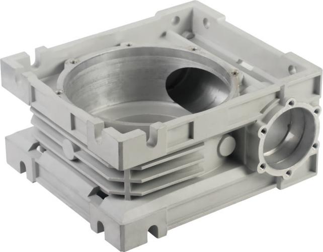
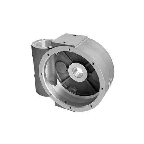
| Single-Cavity Die | One cavity (produces one part per cycle). | Low-to-mid volume (1,000–10,000 units), large/complex parts (e.g., automotive transmission housings) where precision is critical. Lower tooling cost for small runs. |
| Multi-Cavity Die | 2–100 cavities (produces multiple identical parts per cycle). | High-volume (10,000+ units), small/simple parts (e.g., zinc zipper pulls, aluminum sensor housings). Lowers per-unit cost by increasing output per cycle. |
3. Specialized Dies
- Slide Die: Uses movable “slides” (side components) to create undercuts or complex features (e.g., holes perpendicular to the die’s opening direction). Common for parts like plastic connector housings or automotive door handles.
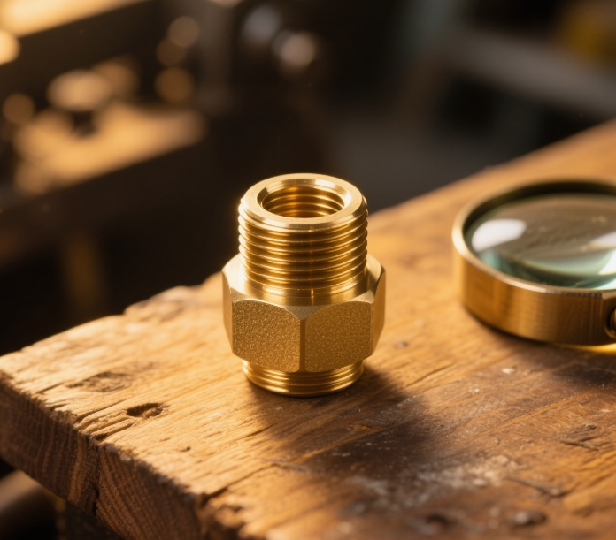
- Collapsible Core Die: For parts with deep internal cavities (e.g., pipe fittings) —a core collapses inward after cooling to allow ejection (avoids breaking the part).
Step 3: Key Materials for Die Cast Molds (Must Withstand Heat & Pressure)
Die materials are chosen for high temperature resistance, wear resistance, and toughness—since dies endure repeated exposure to molten metal (380–700°C) and high pressure. The two most common materials are:
1. H13 Tool Steel (Most Common for High-Volume Production)
- Composition: Chromium (5%), molybdenum (1.5%), vanadium (1%)—alloyed with steel for strength.
- Key Traits:
- Heat resistance: Withstands up to 650°C (ideal for aluminum/magnesium die casting).
- Wear resistance: Hardens to HRC 44–48 (Rockwell hardness) after heat treatment—handles millions of cycles.
- Toughness: Resists cracking from thermal shock (rapid heating/cooling).
- Best For: High-volume production (100,000+ parts), aluminum/magnesium alloys (higher melting points). Tooling cost: $10,000–$100,000+ (depending on size/complexity).
2. P20 Pre-Hardened Steel (For Mid-Volume Production)
- Composition: Chromium (1.5%), manganese (1%)—pre-hardened to HRC 28–32 at the factory (no post-machining heat treatment).
- Key Traits:
- Easier to machine than H13 (faster die production).
- Lower heat resistance (max 450°C)—only suitable for zinc die casting (lower melting point: 380–420°C).
- Lower cost than H13 (20–30% cheaper).
- Best For: Mid-volume production (10,000–100,000 parts), zinc alloys (e.g., toy models, zinc hardware). Tooling cost: $5,000–$50,000.
3. Other Rare Materials
- Stainless Steel (420): For corrosion-prone applications (e.g., marine parts)—resists rust from cooling water, but higher cost than H13.
- Copper Alloys: For ultra-high-temperature die casting (rare today, replaced by H13).
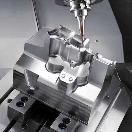
Step 4: How Die Cast Molds Are Manufactured (Precision Is Critical)
Die manufacturing is a multi-step process requiring tight tolerances (±0.005mm) to ensure part accuracy. Here’s the typical workflow:
-
Design (CAD/CAM):
- Engineers use 3D CAD software (e.g., SolidWorks, AutoCAD) to design the die’s cavity, gating, and cooling systems—matching the part’s 3D model.
- CAM software converts the design into machine code for CNC equipment.
-
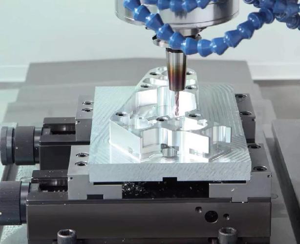
Rough Machining:
- Blocks of H13/P20 steel are cut into the die’s basic shape using CNC milling machines—removing 70–80% of excess material.
-
Precision Machining:
- EDM (Electrical Discharge Machining): Uses electrical sparks to cut complex cavities, undercuts, or small features (e.g., 0.5mm vents) that CNC milling can’t reach. Critical for intricate parts like electronics housings.
- Wire EDM: Cuts precise slots or holes (e.g., for ejector pins) with tolerances as tight as ±0.001mm.
-
Heat Treatment:
- H13 steel is heated to 1,050°C (quenched) then tempered at 500–600°C to reach HRC 44–48—hardening it for wear resistance.
- P20 steel skips this step (pre-hardened).
-
Finishing:
- Polishing: The cavity is polished to Ra 0.8–1.6 μm (smooth surface) to ensure the part has a clean finish (no die lines).
- Assembly: Ejector pins, cooling channels, and slides are installed—tested for alignment and movement.
-
Trial Runs (Die Tryout):
- The die is mounted on a die casting machine, and 50–100 test parts are produced. Engineers check for defects (porosity, misalignment) and adjust the die (e.g., widen vents, tweak gate size) before full production.
Step 5: Die Life Cycle & Maintenance (Maximize Longevity)
A die’s lifespan depends on material, maintenance, and production volume—but with proper care, H13 dies can last 500,000–2,000,000 cycles (aluminum casting) or 1,000,000–5,000,000 cycles (zinc casting).
Key Factors That Shorten Die Life
- Thermal Shock: Rapid temperature changes (e.g., cold die + hot metal) cause cracking.
- Wear: Molten metal erodes the cavity over time (worse with aluminum, which is abrasive).
- Poor Maintenance: Lack of cleaning or lubrication leads to stuck parts and die damage.
Essential Maintenance Practices
- Clean After Each Shift: Remove leftover metal (flash) from the cavity and gating system with non-abrasive tools (brushes, air blowers).
- Lubricate Ejection System: Apply high-temperature lubricant to ejector pins/slides to prevent sticking.
- Inspect Regularly: Check for cracks, wear, or misalignment—repair small issues (e.g., polish worn cavities) before they worsen.
- Store Properly: If unused, coat the die with anti-rust oil and store in a dry environment to prevent corrosion.
Step 6: Common Myths About Die Cast Molds
-
Myth: “Die casting molds are the same as injection molding molds.”
Fact: Injection molding molds use plastic (low temperature/pressure), while die casting molds use metal (high temperature/pressure)—die molds are thicker, made of harder steel (H13 vs. P20 for plastic), and include cooling/venting systems tailored to molten metal. -
Myth: “Multi-cavity dies are always cheaper per part.”
Fact: Multi-cavity dies have higher upfront costs (e.g., a 4-cavity die costs 3x more than a single-cavity die). They only lower per-unit costs if production volume exceeds 10,000 units—for small runs, single-cavity dies are cheaper. -
Myth: “Die hardening = better performance.”
Fact: Over-hardening H13 steel (above HRC 48) makes it brittle—prone to cracking from thermal shock. The ideal hardness (HRC 44–48) balances wear resistance and toughness. -
Myth: “Die defects can be fixed with post-processing.”
Fact: Die issues (e.g., misaligned cavities, poor venting) cause permanent part defects (e.g., warping, porosity) that can’t be fixed by trimming or painting. Die tryouts are critical to catch these issues early.
Step 7: How to Choose the Right Die for Your Project
Follow this checklist to avoid costly mistakes:
- Match Die Material to Alloy:
- Aluminum/magnesium → H13 steel (heat resistance).
- Zinc → P20 steel (cost-effective, easier machining).
- Choose Cavity Count Based on Volume:
- <10,000 units → Single-cavity die.
10,000 units → Multi-cavity die (2–8 cavities for most parts).
- <10,000 units → Single-cavity die.
- Prioritize Die Tryout:
- Always request 50–100 test parts to check for defects—adjust the die before full production.
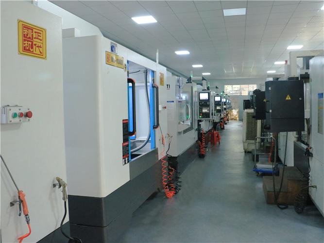
- Work With Experienced Die Makers:
- Look for suppliers with ISO 9001 certification and experience in your industry (e.g., automotive, medical)—they’ll optimize the die design for your part’s needs.
Final Takeaway
The die (mold) is the backbone of die casting—its design, material, and maintenance directly determine part quality, production speed, and cost. For most projects:
- Use H13 steel dies for high-volume aluminum/magnesium parts.
- Use P20 steel dies for mid-volume zinc parts.
- Opt for multi-cavity dies only if production exceeds 10,000 units.
If you’re unsure about die design (e.g., “Do I need a slide die for my part’s undercut?”), share your part’s 3D model or specifications in the comments—we’ll help you select the right die configuration!