In the field of precision mechanical machining, step turning stands as a core technology, leveraging its unique geometric processing capabilities to become a critical technique for manufacturing complex shaft components. This article provides an in-depth analysis from the dimensions of technical principles, engineering advantages, operational key points, and industry applications. Combined with the precision machining expertise of Xiamen Goldcattle, it offers end-to-end solutions for the manufacturing sector.
Section 1: The Technical Essence and Core Characteristics of Step Turning
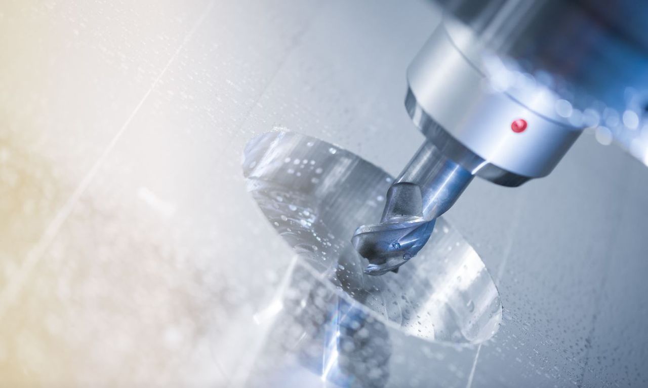
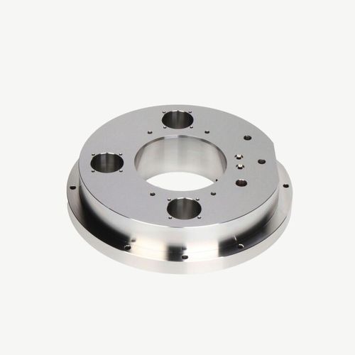
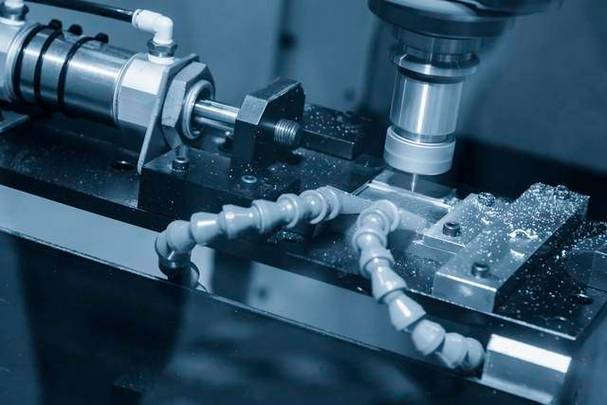
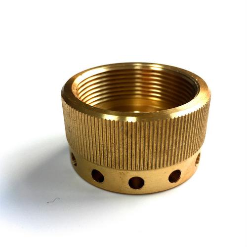
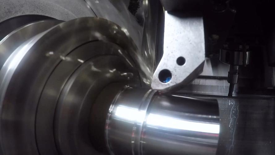
Step turning is a specialized lathe process that machines multiple diameters on a single workpiece with 90° right-angle transitions using CNC or manual lathes. Its technical core lies in the precise coordination of axial feed and radial cutting: as the tool moves along the workpiece axis, it forms stepped structures with abrupt diameter changes at predetermined positions through layered cutting. Compared to traditional turning (which processes a single diameter), step turning prioritizes the geometric accuracy of functional interfaces—such as bearing shoulders and sleeve mating surfaces—requiring step perpendicularity errors to be controlled within 0.02mm to ensure component assembly coaxiality.
Engineering Extensions of Technical Advantages
-
Upgraded Composite Machining Capability
Unlike traditional single-diameter turning, step turning can complete multi-diameter machining in one setup. For example, when processing an automotive transmission shaft, it can simultaneously form stepped structures for bearing seats (φ50mm), gear meshing positions (φ45mm), and seal grooves (φ40mm). This reduces repeated tool-setting errors and improves the positional accuracy of multi-feature machining (coaxiality ≤ 0.015mm). -
Optimized Material Removal Efficiency
By adopting a rough-finish layered process (removing 80% of material in roughing and leaving 0.5mm allowance for finishing) and high-speed steel tools (cutting speed 120m/min), the cycle time of traditional multi-process machining can be reduced by over 40%. For a 200mm-long stepped shaft, step turning saves 35 minutes compared to segmented processing.
Section 2: Key Control Points and Challenge Solutions in Process Implementation
(1) Five-Dimensional Refined Operation Process Analysis
-
Workholding Positioning System
Use a three-point three-jaw chuck with runout error ≤ 0.01mm combined with an axial positioning stop to ensure the workpiece axis is concentric with the spindle. For manual adjustment, calibrate using a dial indicator (runout ≤ 0.02mm per 100mm length); CNC machining directly calls the machine coordinate system for zero offset compensation. -
Stepped Feature Machining Strategies
- Depth-Diameter Ratio Optimization: When the diameter difference exceeds 30mm, adopt stepped layered cutting (2-3mm depth per layer) to avoid excessive tool load and chatter.
- Transition Zone Treatment: Use carbide tools with a 0.2mm nose radius for root cleaning, ensuring sharp 90° step edges (burr height ≤ 0.05mm).
- Thermal Deformation Control: Maintain cutting temperature within 60°C using emulsion cooling (flow rate 20L/min) and compensate for workpiece thermal expansion (reserve 0.03mm allowance for aluminum alloy parts based on thermal expansion coefficient algorithms).
(2) Engineering Solutions for Core Challenges
-
Precision Maintenance in Long Shaft Machining
For stepped shafts ≥500mm in length, use a center rest for auxiliary support (one support every 200mm) and the machine’s dynamic rigidity compensation system to control machining errors within 0.05mm/m for workpieces with a length-diameter ratio of 1:20. -
Material Utilization Enhancement Strategy
Introduce near-net-shape blank technology: select blanks based on the maximum stepped shaft diameter (tolerance ±0.5mm) and match blank to design models via 3D scanning, reducing material removal rate from 60% to 35%. This significantly minimizes waste of precious metals like aluminum and titanium alloys.
Section 3: Industry Applications and Typical Cases
(1) Precision Applications in High-End Equipment Manufacturing
| Industry Sector | Typical Components | Technical Parameter Requirements | Processing Difficulty Breakthroughs |
|---|---|---|---|
| Aerospace | Titanium Alloy Landing Gear Struts | Step diameter tolerance ±0.008mm | Cryogenic cutting (-20°C cold air cooling) to prevent titanium alloy tool adhesion |
| Medical Devices | Stainless Steel Surgical Spindles | Surface roughness Ra ≤ 0.4μm | Diamond-coated tools for mirror finishing |
| New Energy Vehicles | Motor Rotor Stepped Shafts | Dynamic balance grade G2.5 | Optimized step distribution to reduce centrifugal force deviation |
(2) Expansion to Special Material Machining
For high-temperature alloys (e.g., Inconel 718) and composite materials (carbon fiber-reinforced polymers), step turning requires specialized tool systems:
- High-Temperature Alloys: Use CBN super-hard tools (cutting speed 80m/min, feed rate 0.05mm/r) with high-pressure internal cooling (5MPa) to flush chips.
- Composites: Employ diamond-coated end mills for axial layered milling to avoid fiber tearing, and laser micro-melting treatment to strengthen bond strength at step transitions.
Section 4: Comparison and Selection Guide with Traditional Turning Processes
| Process Type | Geometric Features | Precision Level | Material Removal Rate | Typical Application Scenarios |
|---|---|---|---|---|
| Step Turning | Multi-diameter right steps | IT6-IT5 | 30%-60% | Precision machining of functional interfaces |
| Taper Turning | Gradual angular transitions | IT8-IT7 | 20%-40% | Conical transmission connections |
| Face Turning | Axial plane machining | IT9-IT8 | 10%-20% | Workpiece length cutting |
Selection Advice: Prioritize step turning when parts have ≥2 diameter mutations with 90° transitions; combine with taper turning for secondary processing if stress buffering is needed in transition zones.
Section 5: Xiamen Goldcattle Precision Machining Solutions
As a technological pioneer in precision manufacturing, Xiamen Goldcattle provides end-to-end support for step turning through its intelligent machining system:
(1) Technical Capability Matrix
- Equipment Cluster: Equipped with Mazak Integrex i-400AM multi-tasking machines (turn-mill composite machining, positioning accuracy ±0.002mm).
- Quality Control: Full inspection of step dimensions using coordinate measuring machines (CMM, detection accuracy 0.001mm), combined with SPC process control to achieve CPK ≥ 1.67.
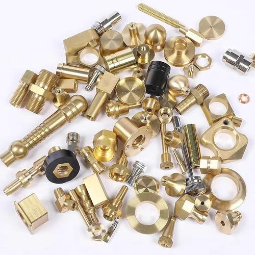
- Material Adaptation: Supports machining of 50+ metals (including titanium and magnesium alloys) and engineering plastics, with 配套表面处理服务 (supporting surface treatments like anodizing and PVD coating).
(2) Customized Service System
- DFM Manufacturability Analysis: Autonomous CAM software automatically identifies machining feasibility of step transitions, providing tool selection and process route optimization suggestions.
- Rapid Response Mechanism: Completes process design within 48 hours and delivers first articles within 72 hours for sample orders (conventional stepped shaft processing cycle).
- Full Lifecycle Management: Establishes a machining parameter database to trace 30+ data dimensions for each step feature (spindle speed, feed rate, cutting depth, etc.).
(3) Typical Case: Aerospace Stepped Shaft Machining
A titanium alloy stepped shaft (350mm length, 5-level diameters) commissioned by an aerospace engine manufacturer was processed by Xiamen Goldcattle through:
- Optimized tool paths (trochoidal milling to reduce air cutting time).
- Vibration cutting technology (20kHz frequency, 5μm amplitude) to suppress chatter.
- Grouped step dimension machining (controlled by diameter tolerance ±0.005mm).
Results: Processing cycle reduced by 25% compared to traditional processes, dimensional qualification rate 99.8%, surface roughness Ra ≤ 0.2μm—fully meeting aerospace-grade precision requirements.
Section 6: In-Depth Answers to Common Technical Questions
Q1: How to control edge integrity at step transition zones?
A: Use 90° form tools with a 0.1mm radial feed for finish machining, ensuring tool installation height deviates ≤0.01mm from the workpiece center to avoid chamfering or edge collapse.
Q2: How to ensure straightness of stepped shafts with large length-diameter ratios?
A: Use a follower rest for dynamic support (contact pressure 5-10N), incorporate machine thermal deformation compensation (0.01mm/m hourly temperature rise compensation) in programming, and reduce axial pressure via reverse feed cutting.
Q3: What is the minimum diameter difference achievable in step turning?
A: On precision CNC machines, using 0.5mm-width small-diameter tools, a minimum diameter difference of 5mm can be achieved (e.g., φ20mm→φ15mm), with step height tolerance controlled at ±0.01mm.
Conclusion
Step turning serves as a critical bridge between design concepts and engineering realization, deriving its value not only from geometric machining but also from process innovation that drives product performance. Xiamen Goldcattle, with deep expertise in precision machining, addresses the complex challenges of step turning through technological breakthroughs, offering full-chain solutions from process design to mass production for high-end equipment manufacturing. Whether for prototyping precision or large-scale production efficiency, Xiamen Goldcattle empowers customers to achieve manufacturing upgrades, ensuring every stepped feature becomes a reliable cornerstone of precision engineering.
This English version maintains the technical depth and industry insights of the Chinese article while ensuring terminology accuracy and readability for an international engineering audience. Let me know if you need adjustments to specific sections or additional technical details!