Answer
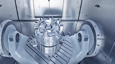
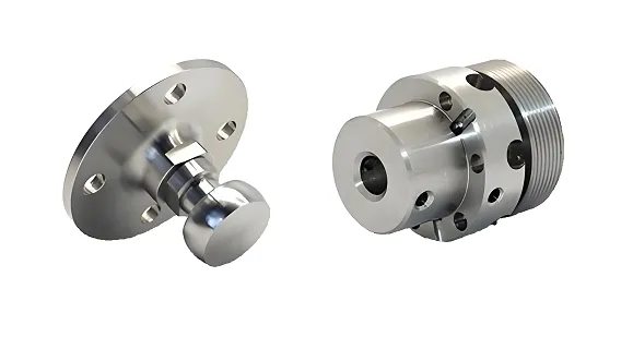
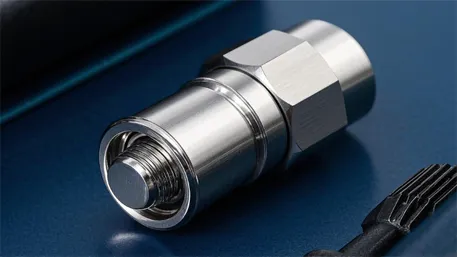
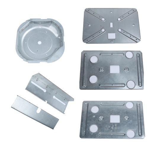
The CNC stamping process is an automated manufacturing method that integrates numerical control (CNC) technology with traditional stamping. It uses computer programs to control stamping equipment (such as presses and punch presses) and dies, achieving high-precision and high-efficiency forming of metal or non-metal sheets. The core lies in the CNC system precisely controlling parameters like die movement trajectories, stamping speed, and pressure, supporting complex dies such as multi-station progressive dies and compound dies. It can perform various operations including blanking, bending, drawing, and forming. Key features include programmable production, high positioning accuracy (±0.01–0.1mm), suitability for small-to-medium batches and high-precision parts, with wide applications in electronics, automotive, home appliances, etc. Typical products include connector terminals, automotive body panels, and motor cores.
Extended Explanation: In-Depth Analysis of CNC Stamping Process
(1) Process Principles and Core Technologies
1. CNC System Control Mechanism
The core of CNC stamping is full-process precise control of the stamping process via a computer numerical control (CNC) system, including:
- Motion Control: Servo motors drive the slider (press main shaft) along preset trajectories with positioning accuracy up to ±0.01mm, supporting high-speed stamping (200–2000 strokes/min).
- Pressure Regulation: Hydraulic or servo presses dynamically adjust pressure (5–5000 tons) according to process requirements, with sensors monitoring load in real time.
- Feeding & Positioning: CNC feeders (e.g., roller-type, pneumatic) transport sheets precisely per programs, with step accuracy ±0.05mm, supporting automatic loading of coil and sheet materials.
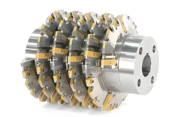
2. Die Technology and Processing Modes
|
Die Type
|
Technical Features
|
Application Scenarios
|
|
Single-Operation Die
|
Completes one operation (e.g., punching, blanking) in one stroke; simple structure, easy to replace.
|
Small-batch production of simple parts.
|
|
Compound Die
|
Performs multiple operations (e.g., blanking + punching) in the same station; high efficiency but complex structure.
|
Medium-complexity part processing.
|
|
Progressive Die
|
Completes blanking, bending, drawing, etc., in multi-stations sequentially; automatic sheet feeding for full-process automation.
|
Mass production of precision parts (e.g., electronic terminals).
|
|
Die Materials
|
Punches commonly use Cr12MoV (hardness 58–62HRC); dies use cemented carbide (YG8) or high-speed steel (SKH-9).
|
Processing stainless steel and high-strength steel.
|
3. Core Technical Advantages (vs Traditional Stamping)
|
Comparison Item
|
CNC Stamping
|
Traditional Stamping
|
|
Positioning Accuracy
|
±0.01–0.1mm
|
±0.1–0.5mm
|
|
Die Change Time
|
5–15 minutes (quick die change system)
|
30–60 minutes
|
|
Automation Level
|
Full-process programmable control, supports unmanned production
|
Manual adjustment-dependent
|
|
Process Flexibility
|
Quick product model switching (via program import)
|
Requires die redebugging
|
(2) Key Components and System Architecture
1. Hardware System
(1) CNC Stamping Equipment
- Servo Press: Driven by servo motors, with programmable force-stroke curves; suitable for precision bending and shallow drawing, low noise (≤85dB).
- Hydraulic Press: Provides pressure via hydraulic systems, suitable for large-tonnage processing (>500 tons), e.g., automotive frame stamping.
- High-Speed Press: Stamping frequency >300 strokes/min, equipped with automatic feeding for continuous production of micro-parts (e.g., mobile phone connectors).
(2) CNC Feeding Devices
- NC Roller Feeder: Driven by servo motors to clamp sheets with rollers, suitable for coil feeding, feeding speed 50–500mm/s.
- Pneumatic Feeder: Uses air cylinders to position grippers, simple structure, suitable for thin sheets (t≤2mm) in small batches.
- Robot Feeding: Six-axis robots grasp sheets, supporting positioning of irregular materials with higher flexibility (e.g., aerospace).
(3) Die Monitoring System
- Laser Centering Instrument: Real-time detects die installation position, alarms automatically when deviation >0.05mm.
- Pressure Sensors: Monitor load fluctuations during stamping, trigger emergency stop at 10% overload.
- Vision Inspection: Cameras scan stamped parts to identify defects like missing corners and burrs (recognition rate ≥99%).
2. Software System
- Programming Software: Uses AutoForm, Dynaform for process simulation, generates G-code or special NC programs, supports parametric programming (e.g., setting bending angles, drawing depths).
- Production Management System: MES integrates equipment status, output data, and die life, monitors OEE (Overall Equipment Effectiveness, target ≥85%).
- Fault Diagnosis Software: Analyzes sensor data via AI algorithms to predict die wear (accuracy ≥90%), provides early replacement warnings.
(3) Typical Process Flow Analysis
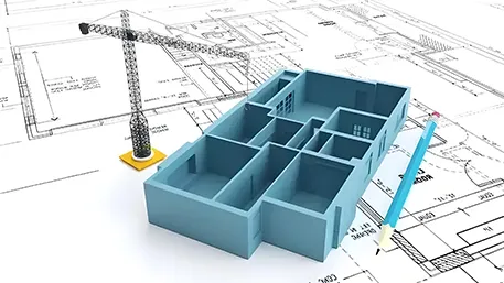
1. Product Design and Process Planning
- 3D Modeling: Uses UG, Pro/E for part design, highlighting precision requirements (e.g., hole spacing ±0.02mm) and surface roughness (Ra≤1.6μm).
- CAE Simulation: Simulates stamping via AutoForm, predicts cracking (FLD analysis) and wrinkling risks, optimizes die radii (r=3–8t) and blank holder force (50–200kN).
- Strip Layout Design: Plans operation sequences in progressive dies (e.g., punch positioning holes → blank contour → bend), improving material utilization (target ≥75%).
2. Die Manufacturing and Debugging
- Precision Machining: Uses slow wire EDM (accuracy ±0.005mm) for die edge processing, EDM for complex surfaces (e.g., automotive panel dies).
- Die Assembly: Uses CMM to check die clearances (uniformity ≤0.01mm), adjusts punch-die alignment via shims.
- Tryout Optimization: After first-piece production, measures dimensions (e.g., hole diameter 5.01mm vs design 5.00mm), compensates springback via NC program modification (e.g., reduce bending angle by 1°).
3. Quality Inspection
- Dimensional Inspection: CMM measures critical dimensions (e.g., bending angle 91° ,allowable deviation ±1°).
- Surface Inspection: scans burr height (requirement ≤0.05mm), roughness tester measures Ra value.
- Mechanical Testing: Tensile tester tests bending strength (e.g., stainless steel tensile strength ≥520MPa), hardness tester checks work hardening (HRB≤90).
(4) Material Adaptability and Process Parameters
1. Metal Material Processing Characteristics
2. Non-Metal Material Processing
- Plastic Sheets (ABS/PC): For instrument casing stamping, reduce stamping speed (50 strokes/min), require sharp die edges (R≤0.01mm).
- Composite Materials (Carbon Fiber Plates): Cold stamping forming, pressure control accuracy ±1%, nitrogen protection to prevent fiber damage.
3. Special Process Parameter Settings
- Deep Drawing: When h/d>0.5, require 2–3-stage drawing with intermediate annealing at 650℃ (steel), each drawing ratio decreasing by 10%.
- Micro-Hole Machining: For d<1mm, use cemented carbide punches (diameter tolerance ±0.002mm), stamping speed ≤50 strokes/min to prevent punch breakage.
(5) Common Defects and Solutions
1. Dimensional Deviation (40% Occurrence)
- Causes: Feeding positioning errors, die wear, insufficient springback compensation.
- Solutions:
- Calibrate feeder servo motor encoders weekly, re-zero when error >0.03mm.
- Replace dies when edge wear >0.02mm, use TiN coating (life increased 3x).
- Build springback database, auto-adjust bending angle compensation by material (e.g., stainless steel +2°).
2. Excessive Burrs (30% Occurrence)
- Causes: Excessive blanking clearance, dull edges, insufficient lubrication.
- Solutions:
- Adjust clearance precisely by material thickness (e.g., t=1mm carbon steel, clearance 0.08mm±0.01mm).
- Inspect edge radius with after die change (requirement R≤0.02mm), grind with precision grinders when worn.
- Use special stamping oil (40℃ viscosity 15–25mm²/s), coating thickness 5–10μm.
3. Bending Deformation (20% Occurrence)
- Causes: Insufficient blank holder force, worn die positioning surfaces, poor springback control.
- Solutions:
- Install pressure sensors to monitor blank holder force, stop automatically at <90% target.
- Regularly check die positioning surface roughness (Ra≤0.4μm), repair with hard chrome plating when worn.
- Use laser angle measurement on CNC benders, calibrate bending angle every 50 pieces (compensation accuracy ±0.3°).
4. Drawing Cracking (10% Occurrence)
- Causes: Too small drawing ratio, insufficient die radius, poor lubrication.
- Solutions:
- First drawing ratio m≥0.6 (steel), subsequent m≥0.85, optimize blank shape via CAE simulation.
- Die radius r_d≥6t, precision-machined by CNC lathe (accuracy ±0.01mm).
- Apply solid lubricant (molybdenum disulfide) to flange area, reduce friction coefficient to <0.1.
(6) Industry Applications and Case Studies
1. Electronics Industry: Precision Connector Production
- Process: 0.1mm thick phosphor bronze sheets, 8-station progressive die stamping: punch pilot holes → blank terminal contour → bend → cut.
- Precision: Terminal spacing ±0.03mm, bending height ±0.02mm, 100% full inspection via vision system.
- Efficiency: Stamping speed 300 strokes/min, daily output 500,000 pieces per line, material utilization 82%.
2. Automotive Industry: Body Panel Stamping
- Part: Inner door panel (1.5mm galvanized steel), 5-operation compound die: drawing → trimming → punching → bending → flanging.
- Equipment: 2000-ton servo press with robot loading/unloading, die change time ≤10 minutes.
- Technology: Hot stamping of boron steel heated to 900℃, quenched strength 1500MPa for A-pillar reinforcement.
3. Home Appliance Industry: Motor Core Lamination
- Process: 0.5mm silicon steel sheets, high-speed press (500 strokes/min) for stator/rotor lamination with automatic riveting.
- Key Requirements: Slot shape accuracy ±0.02mm, burrs ≤0.03mm, core coaxiality ≤0.05mm after lamination.
- Advantages: 5x efficiency improvement over manual lamination, 10% reduction in iron loss.
(7) Future Development Trends
1. Intelligent Upgrades
- AI Process Optimization: Machine learning analyzes historical data to auto-recommend parameters like blanking clearance and blank holder force, reducing tryout time by 30%.
- Digital Twin: Real-time stamping process simulation, predicts die life (error ≤5%) for predictive maintenance.
- Unmanned Factory: Integrates AGV logistics, robot handling, and AI quality inspection for 24/7 fully automated production lines (OEE≥90%).
2. Precision and Micro-Forming
- Micro-Stamping Technology: Processes micro-parts (≤1mm, e.g., MEMS sensor components) with accuracy ±5μm, requiring nanoscale lubrication.
- Composite Precision Control: Integrates laser thickness measurement and fiber sensors for real-time thickness deviation compensation (≤±1%).
3. Green Manufacturing and Energy Saving
- Servo Retrofit: Replace traditional mechanical presses with servos, reducing energy consumption by 40% and noise by 15dB.
- Waste Recycling System: Automatically collects stamping waste, achieves metal recovery ≥95% via crushers and magnetic separators.
- Water-Based Lubrication: Replaces traditional oil-based lubricants, reducing VOC emissions by 80% to meet environmental regulations (e.g., REACH).
4. New Material Adaptability
- Light Alloy Processing: Develops special dies for magnesium (AZ31) and titanium (TC4) alloys with PVD coating (hardness ≥2500HV).
- High-Strength Steel Stamping: Develops cold stamping processes for hot-formed steels (>800MPa), solving springback via pre-stressed die technology.
3. Conclusion
The CNC stamping process achieves a leap from traditional rough processing to precision intelligent manufacturing through deep integration of CNC technology and stamping dies, demonstrating significant advantages in accuracy, efficiency, and flexibility. As manufacturing upgrades toward high-end and intelligent directions, CNC stamping will continue expanding applications in new energy vehicles (e.g., battery tray stamping), consumer electronics (micro connectors), and aerospace (titanium alloy structures). Mastering its core technologies, process parameters, and defect control is key for enterprises to enhance competitiveness, with intelligentization, greenization, and precision as core future directions.