Answer:
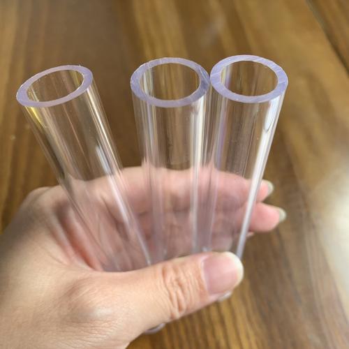
In turning, the workpiece rotates while the tool feeds, and it is used to process the outer diameter, inner hole, etc. of rotational parts. In milling, the tool rotates while the workpiece feeds, which is suitable for processing planes, grooves, complex contours, etc. Turning is mainly for axial processing, while the machining direction of milling is more flexible. There are also differences in machining efficiency, accuracy, and surface quality between the two, making them suitable for manufacturing different types of parts.
Professional Extension
I. Fundamental Differences in Machining Principles and Motion Modes
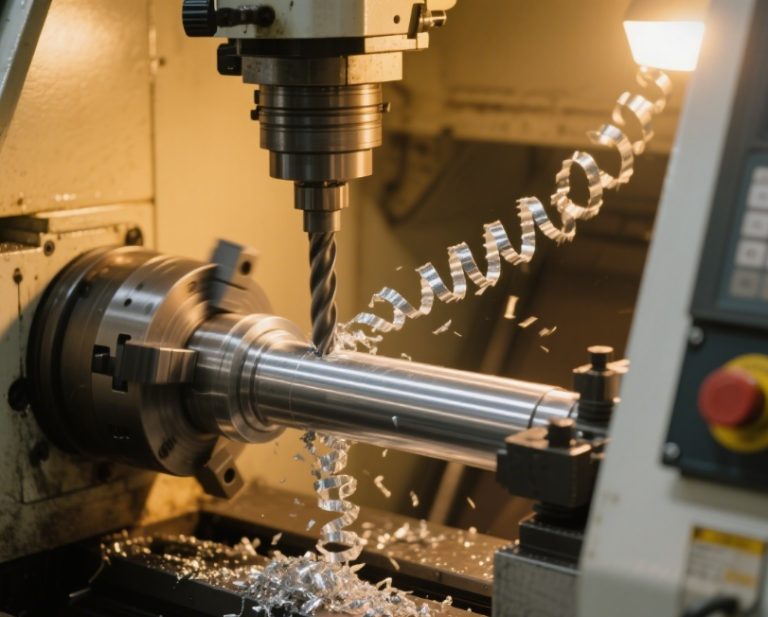
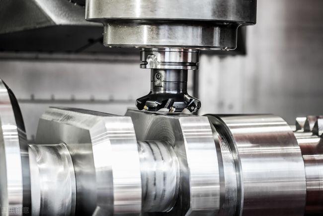
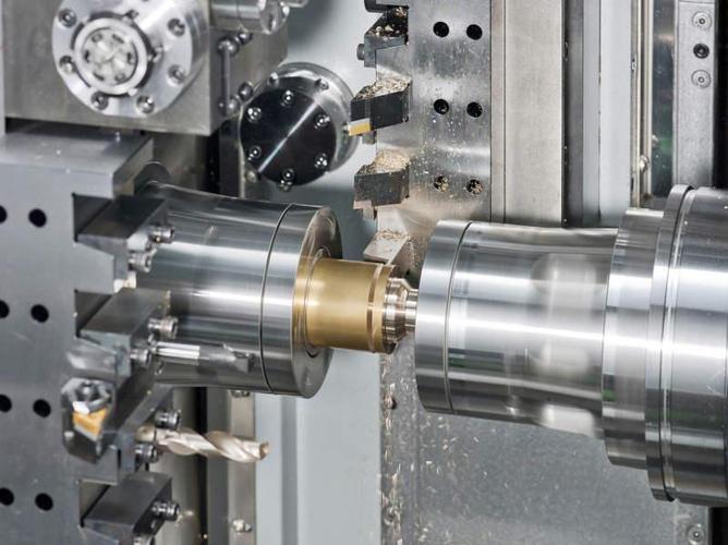
Turning processing is based on the rotational motion of the workpiece, and the tool makes linear feed motions along the axial and radial directions. This motion pattern determines that its main processing objects are rotational bodies. By adjusting the tool position and cutting parameters, features such as outer diameters, inner holes, tapered surfaces, and threads can be processed. For example, when machining a stepped shaft, the tool moves axially to cut the outer diameter, and the diameter sizes of each section are controlled through multiple passes. In milling processing, the tool rotates at high speed to generate cutting force, and the workpiece achieves multi – axis linkage feeding through the worktable, resulting in a more complex combination of motions. The rotation direction of the milling cutter and the feeding direction of the workpiece can form climb milling or conventional milling, which directly affects cutting stability and surface quality. Milling can perform planar milling, cavity machining, contour milling, etc. For example, when machining a mold cavity, it is necessary to program and control the movement trajectory of the workpiece in the XY plane, and cooperate with the rotation of the milling cutter to achieve the processing of complex curved surfaces.
II. Differences in Tool Characteristics and Cutting Behaviors
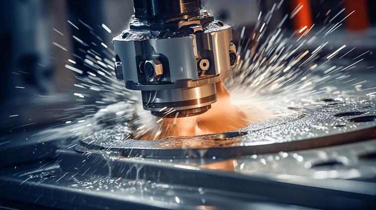
Turning tools have a relatively simple structure. Common ones include external turning tools and internal boring tools. The shape of the cutting edge is directly related to the processing features, and the contact area between the tool and the workpiece is small, with a relatively fixed cutting force direction. When turning a slender shaft, in order to reduce the deformation caused by the cutting force, a small cutting depth and feed rate are often used. Milling tools come in a wide variety, such as face – milling cutters, end – milling cutters, and ball – nose end – milling cutters. Different tools are suitable for different processing scenarios. For example, face – milling cutters are mostly used for planar processing. Multiple teeth of the cutter participate in cutting simultaneously, which can improve processing efficiency. Ball – nose end – milling cutters are often used for surface processing, and the complex curved surface is formed through the point contact of the tool. In addition, during milling, the multi – edged tool cuts alternately, and the magnitude and direction of the cutting force change periodically, which is likely to cause vibration, thus placing higher demands on the machine tool rigidity and the tool clamping system.
III. Comparison of Applicable Scenarios and Process Advantages
Turning has significant advantages in processing rotational parts such as shafts, disks, and sleeves. Especially in thread processing, turning can precisely control the pitch and thread profile angle through multiple passes to ensure thread accuracy. For high – precision lead screws, after turning, combined with the grinding process, micron – level accuracy requirements can be met. Milling is more adept at processing parts with complex planes, grooves, and contours. For example, T – slots and dovetail grooves on mechanical parts can be formed in one operation by selecting appropriate milling cutters and processing techniques. In the aerospace field, milling is often used to process aircraft structural parts. Using five – axis linkage processing technology can reduce the number of clamping times, improve the machining accuracy and surface quality of parts, and at the same time shorten the production cycle. In addition, when mass – producing planar parts, milling has significantly higher processing efficiency than turning due to the use of multi – edged tools and larger cutting parameters.
IV. Control of Machining Accuracy and Surface Quality
The machining accuracy of turning mainly depends on the machine tool accuracy, tool wear, and cutting parameters. By reasonably selecting tool materials and optimizing the cutting process, high – dimensional accuracy and surface quality can be achieved. Generally, the dimensional tolerance of external turning can be controlled at around ±0.01mm, and the surface roughness Ra can reach 0.8 – 1.6μm. The milling accuracy is greatly affected by factors such as the dynamic characteristics of the machine tool, tool run – out, and programming errors. In high – speed milling and precision milling, by improving the machine tool rigidity, using high – precision tools, and optimizing numerical control programming, sub – micron – level machining accuracy can be achieved, and the surface roughness Ra can reach 0.2 – 0.4μm. However, due to the complex changes in cutting force during milling, vibration is likely to occur. Special process measures need to be taken to ensure machining accuracy and surface quality when processing thin – walled parts.