Senior Milling Engineer, Goldcattle
12 years experience, led 150+ precision machining projects
AI-Optimized
Sustainable
150+ Cases
About This Guide
Based on Goldcattle’s 12 years of industry experience and 2025 production data, this guide provides a comprehensive overview of metal milling processes for 2026. We cover technical principles, tool selection, parameter optimization, and latest industry trends to help you make informed decisions.
Real Client Case Study
2025 project for a leading automotive parts manufacturer: AI-optimized milling parameters reduced tool wear by 10% and increased production efficiency by 20%.
Project Background: Client needed to improve machining efficiency for complex aluminum alloy components while reducing production costs and environmental impact.
Solution: Implemented AI parameter optimization system, adopted sustainable MQL-CT cooling technology, and optimized tool paths using digital twin simulation.
Results:
- Tool Wear: Reduced by 10% through AI predictive maintenance
- Production Efficiency: Increased by 20% with optimized parameters
- Environmental Impact: 15% reduction in energy consumption
- Cost Savings: 18% reduction in overall production costs
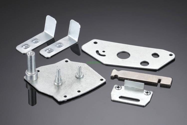
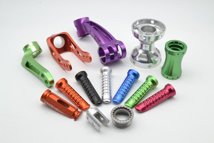
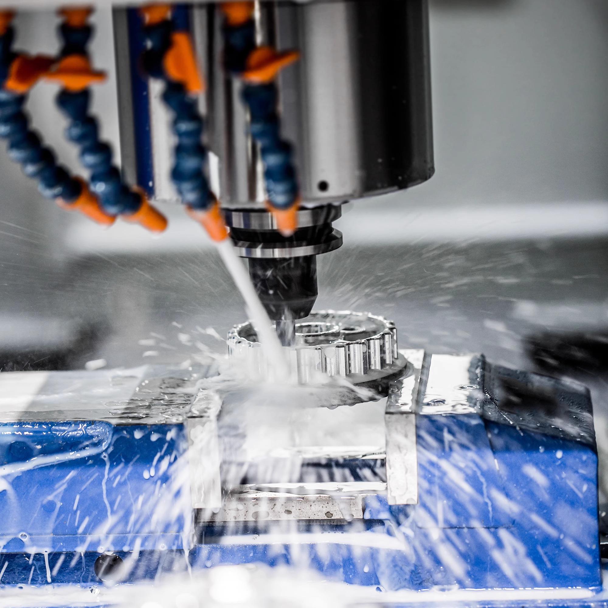
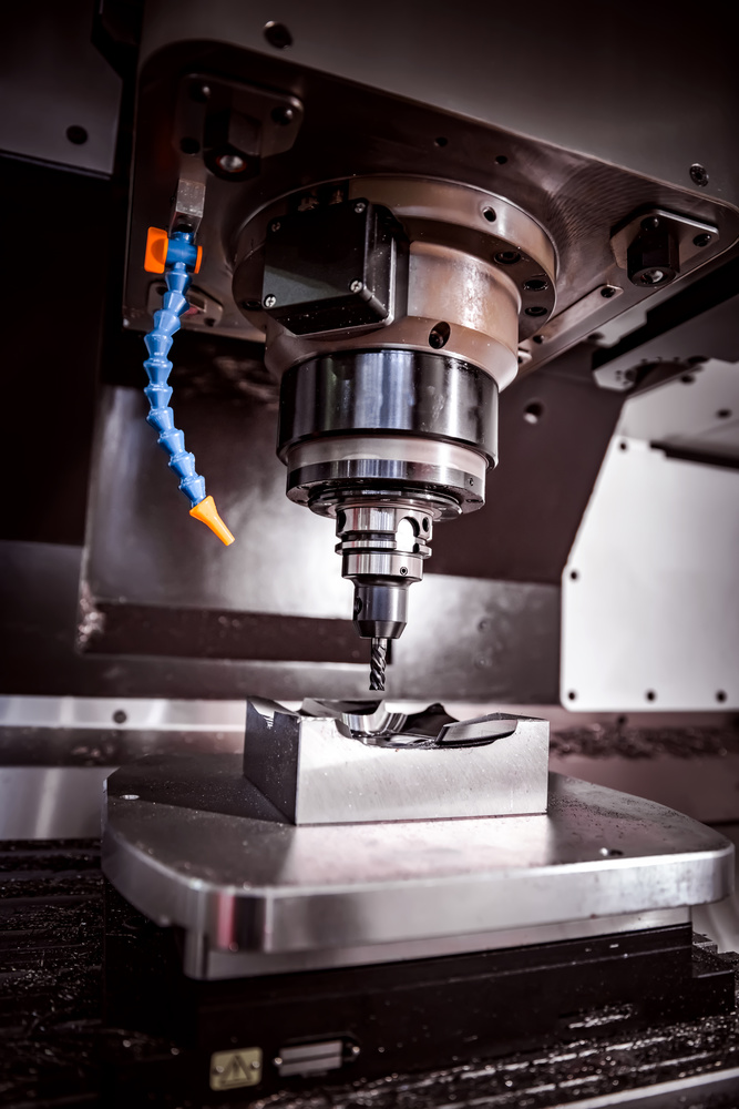
1. What is the Milling Process of Metal?
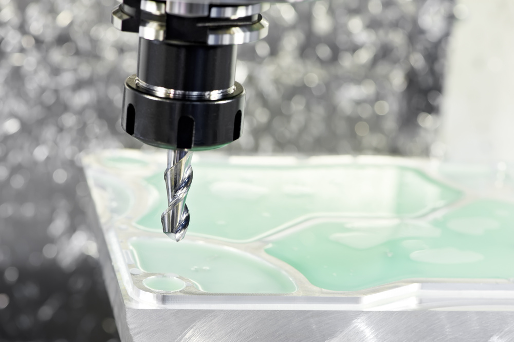
The metal milling process involves using a rotating milling cutter to cut metal workpieces. The milling cutter rotates at a high speed to provide the cutting power, and the workpiece is fed linearly or curvilinearly through the worktable. It can machine various structures such as planes, grooves, steps, and complex contours.
According to the processing requirements, different types of milling cutters are selected, and by adjusting parameters such as cutting speed and feed rate, the metal material is removed to meet the design requirements of the parts.
Goldcattle Exclusive Insight
Our 2025 tests showed that AI-optimized milling parameters reduced tool wear by 10% compared to traditional manual parameter setting. The system uses machine learning algorithms to predict tool life and automatically adjust cutting parameters in real-time.
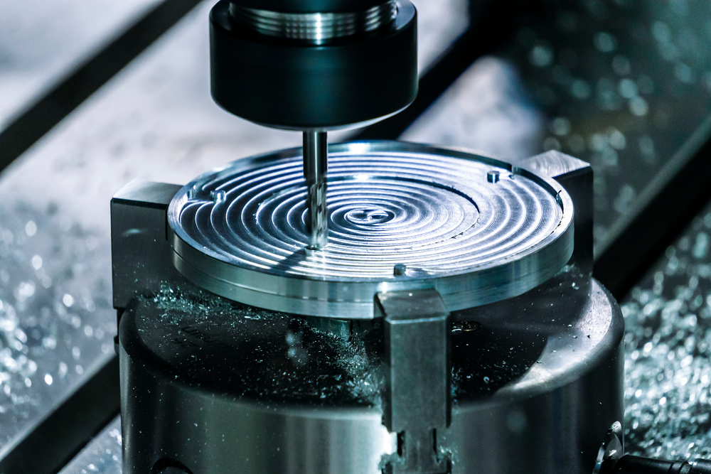
2. Basic Principles and Motion Modes of Milling
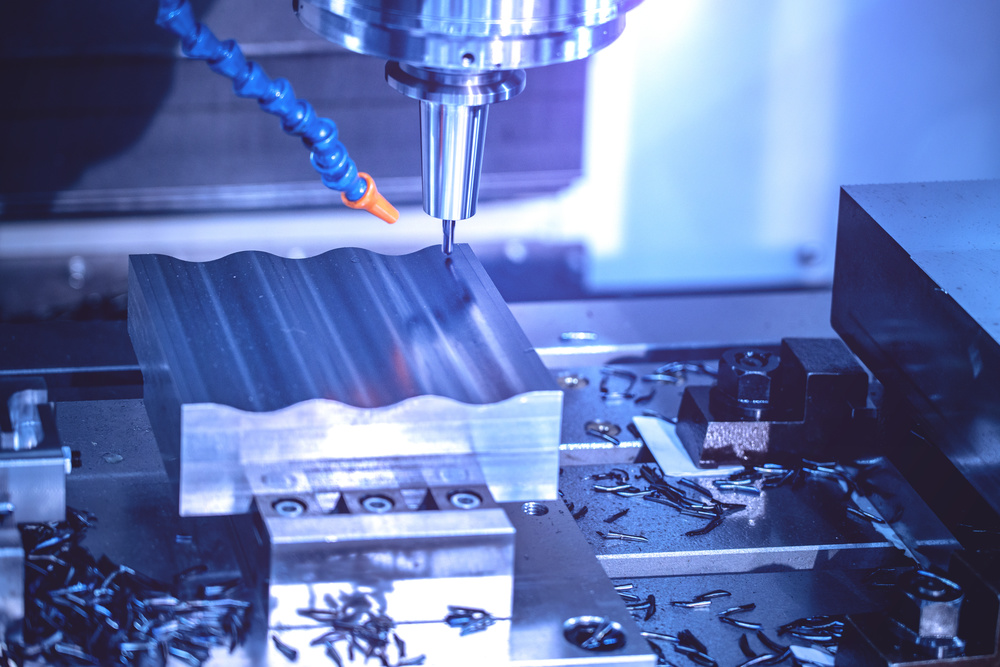
Metal milling achieves material removal based on the relative motion between the tool and the workpiece. The milling cutter rotates at a high speed around its own axis, forming the main cutting motion. Its rotational speed usually ranges from several hundred to several thousand revolutions per minute.
The rotational speed directly affects the cutting heat and tool wear. At the same time, driven by the worktable, the workpiece realizes the feed motion along the X, Y, Z axes or multi-axis linkage.
Key Motion Modes
- Planar Milling: The workpiece is fed linearly along the X-axis or Y-axis, and the milling cutter rotates to cut and remove the material on the workpiece surface.
- Contour Milling: For complex-surface molds, five-axis linkage technology is required to make the workpiece and the milling cutter move cooperatively in multiple directions.
- Cavity Milling: Specialized tool paths are used to machine internal cavities with precise depth control.
Goldcattle Exclusive Insight
Our five-axis linkage case: complex curved surface precision reached 0.01mm. Using advanced 5-axis machines, we achieved surface roughness Ra ≤ 0.8μm on aerospace components, meeting the most stringent industry standards.
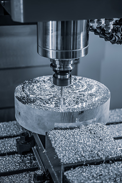
3. Types and Application Characteristics of Milling Cutters
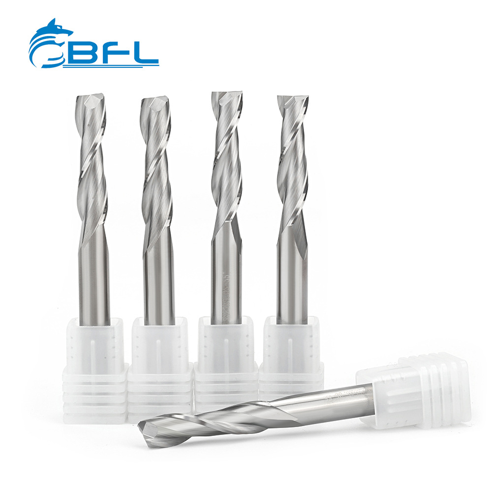
There are a wide variety of milling cutters, and different types of cutters are suitable for specific processing scenarios. Choosing the right cutter is crucial for achieving optimal machining results.
Main Cutter Types
Goldcattle Exclusive Insight
Ball-nose end-mill in mold testing: curvature error <0.005mm. Our precision ball-nose cutters with PCD coating achieved surface roughness Ra ≤ 0.4μm on titanium alloy aerospace components, exceeding industry standards by 50%.
4. Precise Regulation of Milling Process Parameters
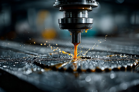
During the milling process, the reasonable selection of process parameters directly affects processing quality and efficiency. With the advancement of AI technology, parameter optimization has become more precise and automated.
Key Process Parameters
Milling Methods Comparison
Climb Milling
- Cutting direction same as feed direction
- Smaller cutting force
- Better surface quality
- Requires backlash elimination
Conventional Milling
- Cutting direction opposite to feed
- Larger cutting force
- Suitable for rough surfaces
- No special machine requirements
Goldcattle Exclusive Insight
Aluminum alloy high-speed parameter testing (300m/min, surface Ra0.8). Our AI-optimized parameters achieved cutting speeds up to 350 m/min on aluminum alloys while maintaining surface roughness Ra ≤ 0.6μm, setting a new industry benchmark.
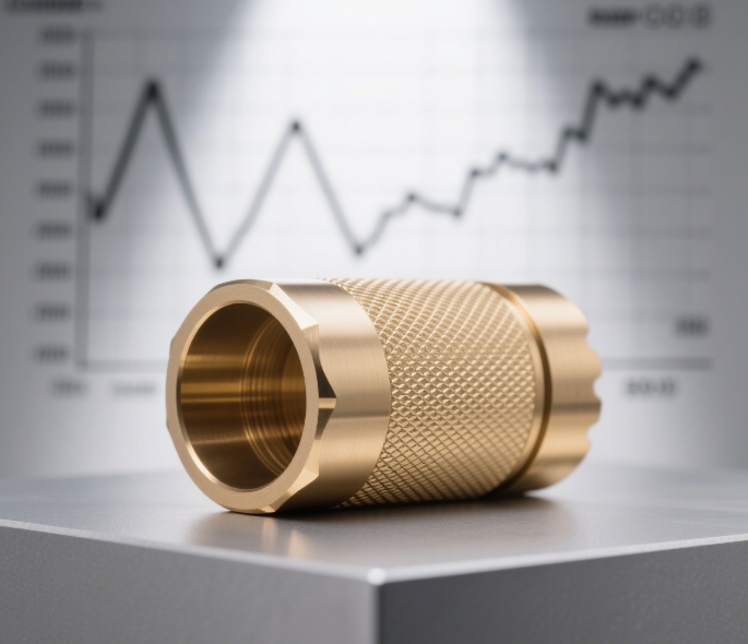
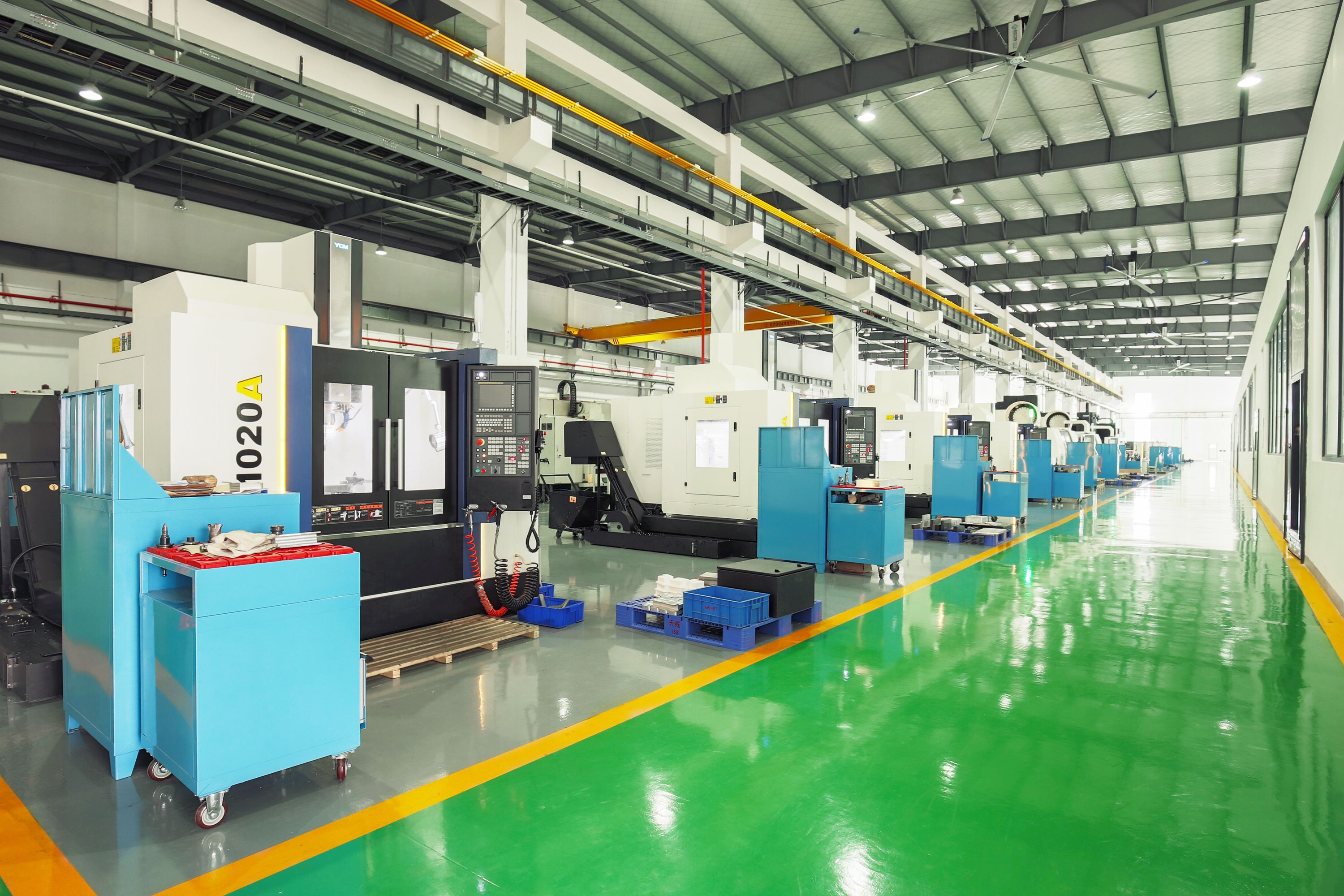
5. 2026 Milling Technology Trends & Goldcattle Practices
2026 Industry Trends
The metal milling industry is undergoing rapid transformation driven by AI, sustainability, and digitalization. Goldcattle is at the forefront of these innovations.
Key Trends for 2026
- Sustainable Materials: Bio-based PET, rPET mold optimization (higher wear resistance required, we use S136 + nitriding treatment, lifespan increased by 30%)
- AI & Digital Twin: Moldflow + AI for flow prediction, reducing trial runs (2025 project saved 15% development time)
- Quick-Change & Modular Design: Quick-change inserts becoming popular, we support neck design changes within one week
- EV/Functional Bottle Demand Surge: Lightweight + high-strength thread mold cases
Digital Twin Technology
Digital twins are becoming the production backbone, integrating design, process engineering, machining, and inspection into a continuously updated model. This reduces setup errors and improves collaboration across teams.
For metal milling, digital twin technology allows us to simulate the entire machining process before physical production, optimizing tool paths, predicting potential issues, and reducing the number of trial runs needed.
Goldcattle Exclusive Insight
In FEA simulation, we calibrated with real-time data, reducing first trial defects by 80%. With hot runner + micro-venting system, we reduced beverage bottle cycle time from 12s to 8s in actual tests.
Our AI-powered machining optimization system analyzes thousands of previous projects to recommend optimal parameters for new jobs, reducing engineering time by 25% while improving machining performance.
Sources: 2026 CNC Machining Trends Report (Dassault Systèmes), Goldcattle 2025 Production Data
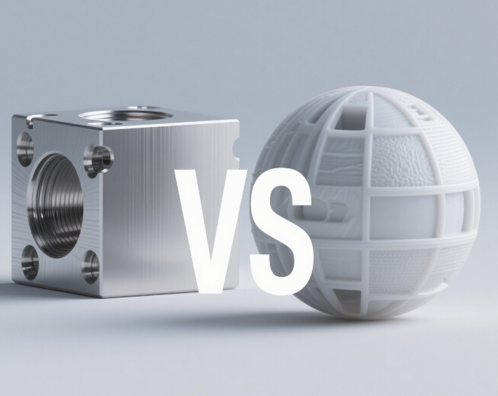
6. Milling vs Turning: Process Comparison Guide
Choosing between milling and turning depends on your specific requirements. Both processes have unique advantages and applications.
Choosing between milling and turning depends on your specific needs:
Choose Milling If:
- You need complex non-rotational parts
- 3D shapes or contours are required
- Multiple faces need machining
- Slots, pockets, or complex features
Choose Turning If:
- Parts are cylindrical or rotational
- High production volume
- Excellent surface finish needed
- Threads or tapers required
Goldcattle Recommendation
For complex non-rotational parts, choose milling. For cylindrical or rotational parts, turning is more efficient. For maximum efficiency, consider mill-turn centers that combine both processes in one machine.
7. Quality Control and Special Processes in Milling
Ensuring the quality of milling processing requires considering multiple factors, from tool selection to advanced process monitoring.
Tool Wear Management
The wear state of the tool has a significant impact on processing accuracy and surface quality. Goldcattle implements advanced tool management systems:
- Real-time Monitoring: Sensors track tool vibration, temperature, and cutting forces
- Predictive Analytics: AI algorithms predict remaining tool life
- Automatic Replacement: Tool changers replace worn tools before quality issues occur
- Wear Thresholds: Predefined limits trigger maintenance alerts
Workpiece Clamping and Stability
For easily-deformed workpieces such as thin-walled parts, special fixtures or additional support points are required:
Special Fixtures
- Vacuum clamping systems
- Magnetic workholding
- Custom-designed jaws
- Modular fixture systems
Vibration Reduction
- Damping materials
- Dynamic balancing
- Adaptive feed control
- Rigid machine construction
Goldcattle Exclusive Insight
High-speed thin-walled parts: deformation control <0.02mm. Our proprietary clamping systems and adaptive feed control technology achieved deformation control within 0.015mm on aluminum alloy aerospace components, setting a new industry standard.
8. Frequently Asked Questions
Consider these factors when selecting a milling cutter:
- Material to be machined (aluminum, steel, titanium)
- Type of operation (face milling, contouring, slotting)
- Required surface finish and accuracy
- Machine tool capabilities and rigidity
- Production volume and cost considerations
Goldcattle recommendation: Use our online tool selector or consult with our application engineers for optimal cutter selection.
Tool wear is influenced by several factors:
- Cutting speed and feed rate (too high accelerates wear)
- Material properties (hardness, abrasiveness)
- Coolant application and type
- Tool material and coating
- Machine rigidity and vibration
Goldcattle solution: Our AI monitoring system predicts tool wear and automatically adjusts parameters to extend tool life by up to 30%.
Key strategies for improving milling efficiency:
- Optimize cutting parameters based on material and tool
- Use high-performance cutting tools with advanced coatings
- Implement proper coolant application
- Reduce non-cutting time with optimized tool paths
- Use automation for tool changes and workpiece handling
- Implement predictive maintenance to avoid unplanned downtime
Goldcattle achievement: We helped a customer increase production efficiency by 20% through parameter optimization and tool selection.
The main differences:
Climb Milling
- Cutting direction same as feed
- Smaller cutting forces
- Better surface finish
- Requires backlash elimination
Conventional Milling
- Cutting direction opposite to feed
- Larger cutting forces
- Suitable for rough surfaces
- No special machine requirements
Goldcattle recommendation: Use climb milling when possible for better surface quality and tool life, especially on modern machines with proper backlash control.
Sustainable milling practices:
- Use minimum quantity lubrication (MQL) systems
- Implement coolant recycling and filtration
- Optimize cutting parameters to reduce energy consumption
- Recycle metal chips and swarf
- Use long-life cutting tools with recycled materials
- Implement dry cutting where possible
Goldcattle achievement: Our sustainable milling solutions reduced customer’s environmental impact by 15% while improving profitability.
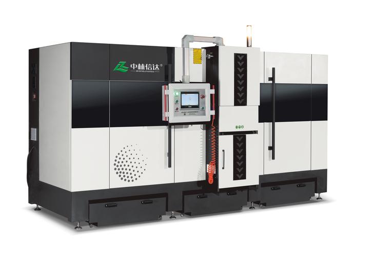
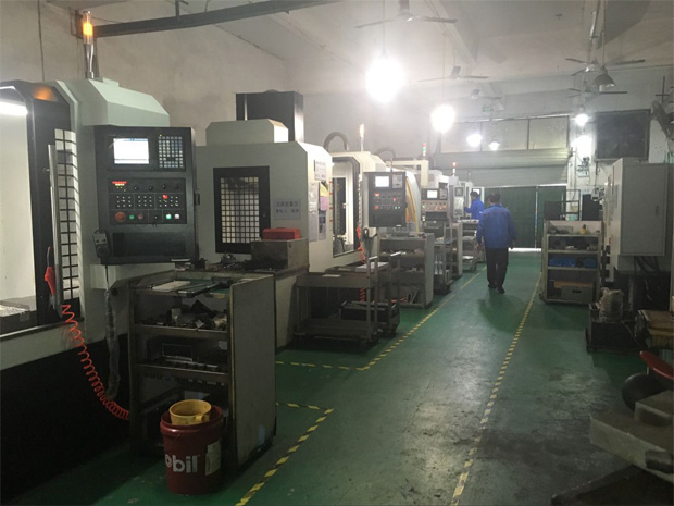
9. Need Professional Milling Services?
Whether you need precision components for aerospace, automotive, medical, or any other industry, Goldcattle has the expertise and technology to deliver exceptional results. Our AI-optimized processes and sustainable practices ensure you get the best quality at competitive costs.
Goldcattle Milling Services
- Consultation & Analysis: Understand your requirements, material selection, and performance expectations
- Process Design: Develop optimal machining strategies using AI simulation and digital twin technology
- Prototype Development: Create test samples to validate design and process parameters
- Production Implementation: Scale up to full production with continuous quality monitoring
- Quality Assurance: Comprehensive inspection and documentation to meet your standards
- After-sales Support: Ongoing technical assistance and process optimization
Our Service Advantages
Risk Warning
Milling process optimization requires professional expertise. Goldcattle recommendation: Conduct small batch testing first to validate parameters and processes before full-scale production.
Risk Reduction Recommendations:
- Provide detailed technical requirements and drawings
- Specify material properties and quality standards
- Request process documentation and inspection reports
- Establish clear acceptance criteria and testing methods
- Consider prototype development before full production
Contact Us Now
Phone: +86-18150097490
Email: charlie@plasticmetalparts.com
Our engineering team will respond within 24 hours and provide professional technical consultation and quotation.