1、Answer
The minimum thickness for machining aluminum typically ranges from 0.5–1 mm (0.02–0.04 in) for most CNC milling/turning operations, but can go lower (e.g., 0.1–0.3 mm) with specialized techniques (e.g., micro-machining, wire EDM) or soft alloys (e.g., 1100 series). Thinner walls require stricter control of tooling, machine rigidity, and cutting parameters to avoid deformation or tool breakage.
2、Expansion
Key Factors Influencing Minimum Thickness
-
Machining Method:
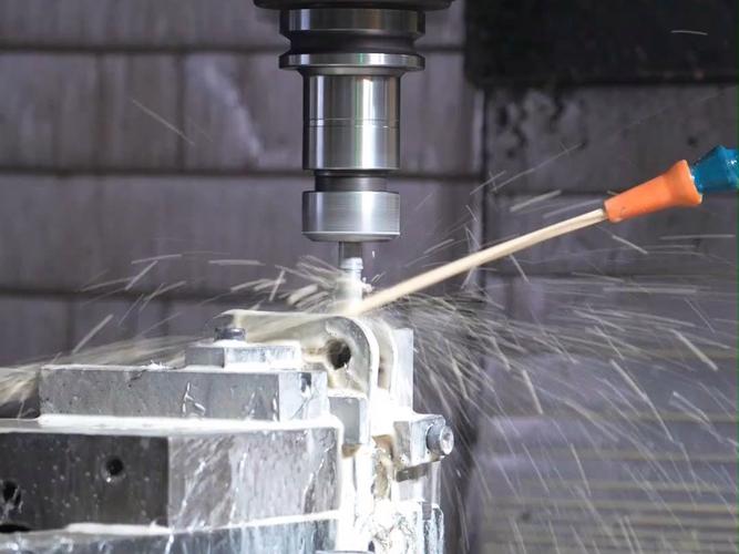
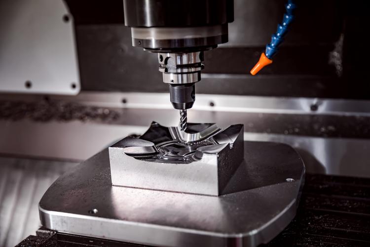
- CNC Milling: Limited by tool diameter (e.g., a 0.5 mm end mill can machine slots as thin as 0.6 mm, accounting for tool deflection). Smaller tools (e.g., 0.1 mm micro-end mills) enable thinner features but are prone to breaking at high speeds.
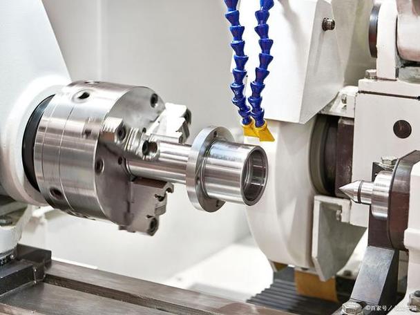
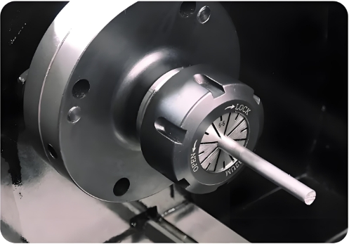
- Turning/Lathe Work: Minimum wall thickness for cylindrical parts is ~0.3 mm, dependent on part diameter and clamping stability.
- Wire EDM: Can achieve <0.1 mm thickness by using ultra-thin wires (e.g., 0.02 mm brass wire) and precise electrical discharge, ideal for intricate, stress-free geometries.
-
Aluminum Alloy Hardness:
- Soft Alloys (e.g., 1100, 3003): Allow thinner walls (e.g., 0.3 mm) due to lower yield strength (~70–110 MPa), reducing risk of plastic deformation during cutting.
- Hard Alloys (e.g., 7075-T6): Require thicker walls (≥0.8 mm) to withstand cutting forces, as their higher hardness (HB ~150) increases tool load and potential for chatter.
-
Design & Geometry:
- ** Unsupported Features**: Thin, standalone walls (e.g., fins on heat sinks) are more prone to vibration. Adding rib supports can reduce minimum thickness by 30–50%.
- Aspect Ratio: A 0.5 mm-thick wall with a 10 mm height is more unstable than a 2 mm-thick wall of the same height, requiring slower feed rates (e.g., 50–100 mm/min vs. 200–300 mm/min) to minimize deflection.
Practical Limits and Trade-offs
- Tooling Constraints:
- Standard HSS end mills struggle below 0.3 mm diameter due to flexure; carbide micro-tools improve rigidity but cost 5–10x more. For example, a 0.2 mm carbide end mill may cost $50 vs. $5 for a 1 mm HSS tool.
- Cutting Parameters:
- Thin features require low axial depth of cut (e.g., 0.1× tool diameter) and high spindle speeds (15,000–40,000 RPM) to reduce heat and tool deflection. Feed rates must be minimized to avoid shearing thin walls (e.g., 0.01–0.05 mm/rev).
- Post-Processing Risks:
- Thinner parts (e.g., <0.5 mm) are more susceptible to warping during heat treatment or anodizing. For instance, a 0.3 mm-thick 6061-T6 bracket may distort 0.05–0.1 mm during aging, affecting tolerances.
Real-World Examples
- Aerospace Components: Turbine blade trailing edges may be machined to 0.4 mm using 5-axis CNC and coolant-assisted carbide tools, with strict vibration-dampening setups.
- Microfluidic Devices: Aluminum channels as thin as 0.15 mm are milled using diamond-coated tools on ultra-precision machines (e.g., Nanotech 350), requiring <5 μm positional accuracy.
- Cost Consideration: Reducing wall thickness from 1 mm to 0.5 mm can increase machining time by 200–300% due to reduced feed rates and multiple finishing passes, offsetting material savings.
Conclusion: While theoretical minimums exist, practical design should prioritize functionality over extreme thinness. For most applications, aim for ≥0.8 mm in hard alloys and ≥0.5 mm in soft alloys. When thinner features are critical, consult with manufacturers to validate feasibility based on their specific machine capabilities and tooling inventory.