CNC Machining Aluminum Warping: Causes and Proven Solutions for High-Precision Parts
Aluminum parts warp during CNC machining mainly due to internal stress, heat buildup, and improper clamping. Effective solutions include stress-relief treatment, optimized machining strategy, and proper fixturing. This engineering guide explains the root causes and actionable fixes to achieve stable, high-precision results for your aluminum components.
Why Aluminum Parts Warp: Root Cause Analysis
 Based on our 20 years of manufacturing experience and analysis of 500+ failure cases, we have identified the 4 core causes of aluminum CNC warping, with clear data-backed proportions:
Proven Engineering Solutions to Prevent Warping
3. Symmetrical Material Removal
For plate or frame parts, always remove material evenly from both sides. This balances the stress release on both sides, preventing the part from bending to one side. For example, when machining a 20mm thick plate to 10mm, remove 5mm from the top and 5mm from the bottom, instead of removing 10mm from one side.
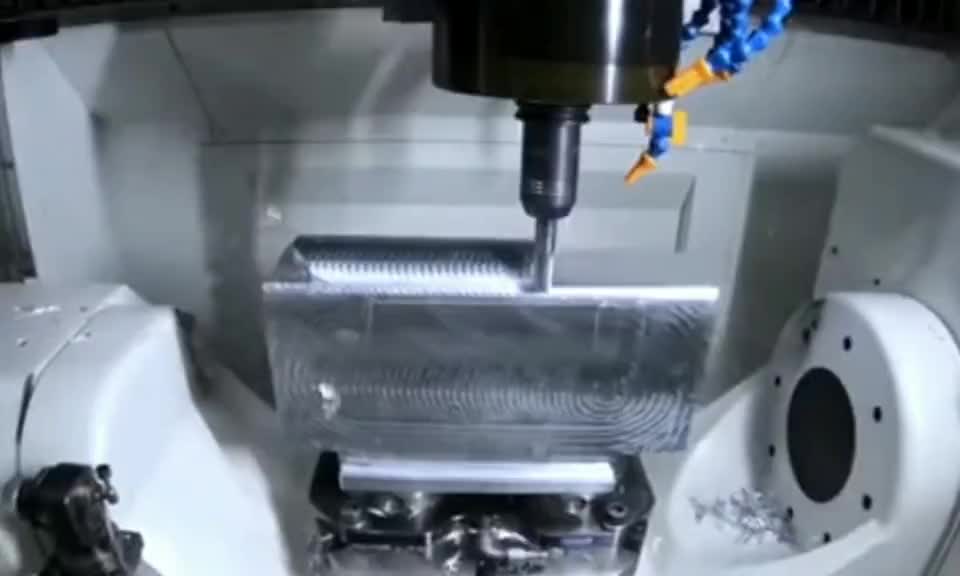
5. Tool Path & Thermal Control
Optimize cutting parameters to minimize force and heat:
- Adopt the “shallow cut, fast feed” strategy: use small cutting depth (0.1-0.5mm) with high spindle speed and moderate feed rate, to reduce cutting force and heat buildup.
- Use sufficient flood coolant to keep the cutting area temperature stable, preventing uneven thermal expansion.
- Use sharp, coated carbide tools to reduce cutting force, which is critical for thin wall parts to avoid “tool push” deformation.
Thin Wall Aluminum Machining: Special Solutions
 Thin wall aluminum parts (wall thickness <2mm) are the most challenging for warping control, as aluminum’s low elastic modulus (70GPa, 1/3 of steel) means they deform 3-4 times more than steel under the same cutting force.
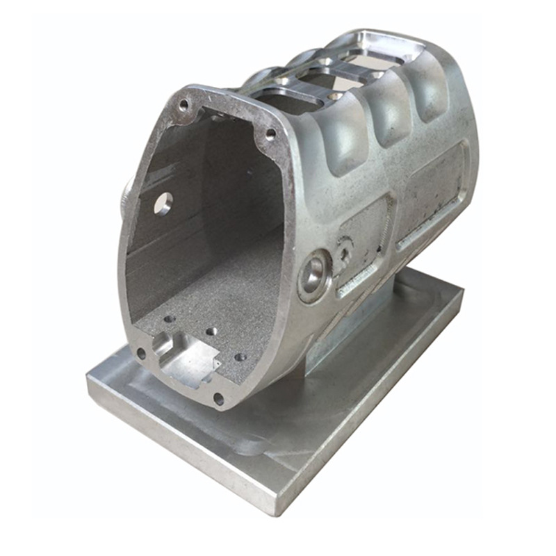
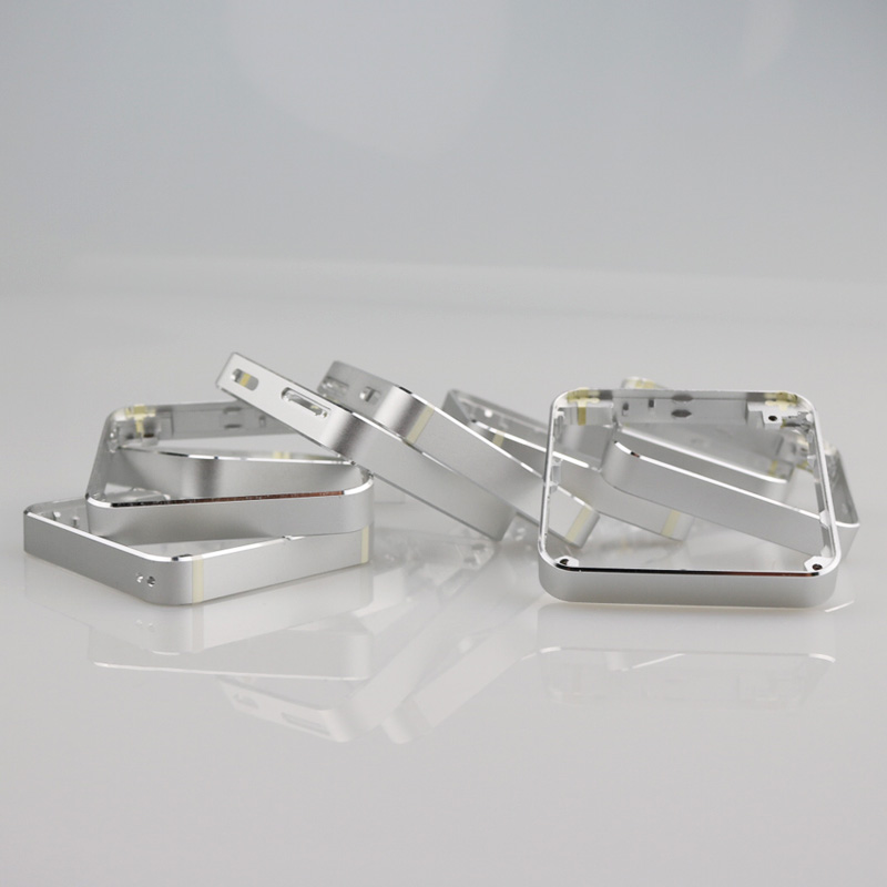
Case Study: Solving Warping for an Aluminum Sensor Housing
The Problem
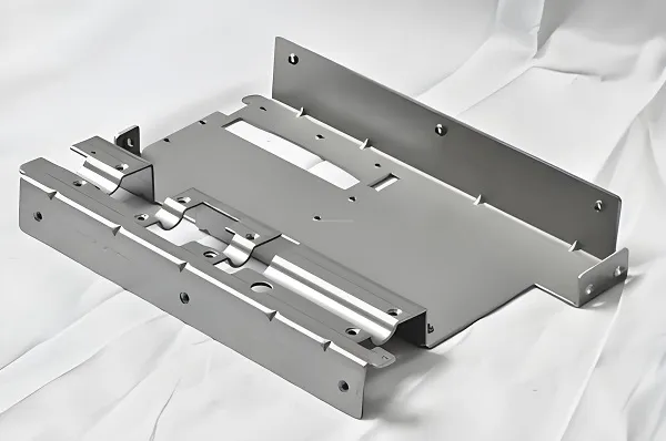
A customer’s 6061 aluminum sensor housing had 0.3mm warping after initial machining, which failed the flatness requirement of 0.08mm. The part had 1.2mm thin walls and a large 150x100mm base plate.
Our Solution
We switched to 6061-T651 stress-relieved material, applied step machining with interim stress relief, and used a custom vacuum fixture with local support pins for the thin wall areas.
The Result
Post-machining warping was reduced to 0.05mm, fully meeting the customer’s precision requirement. The part passed all functional tests with 100% yield in mass production.
Relevant Industry & Execution Standards
- ISO 230-1:2012 – Machine tool accuracy testing standard, ensuring our machining equipment has sufficient positioning accuracy to avoid process errors.
- ISO 8062:1994 – Casting and machining dimensional tolerance standard, guiding our precision control for aluminum parts.
- Internal Standard: SPC-001 – Fixturing deformation inspection standard, requiring pre-machining fixturing error ≤0.01mm.
- Internal Standard: WM-003 – Thin wall part machining standard, defining warping control limits for different wall thickness ranges.
Frequently Asked Questions
Q: Why does aluminum warp during CNC machining?
Aluminum warps mainly due to the release of internal residual stress from the raw material, uneven thermal expansion from cutting heat, improper clamping force, and unbalanced material removal during machining.
Q: How to prevent warping in thin wall aluminum parts?
For thin wall parts, use stress-relieved T651 material, vacuum fixtures for uniform clamping, temporary support filling, small cutting depth parameters, and step machining to release stress in advance.
Q: Which aluminum is best for precision CNC machining to avoid warping?
6061-T651 and 7075-T651 are the best choices, as their stress-relieved temper minimizes post-machining deformation, while providing good strength and machinability.
Q: Can warping be fully eliminated in aluminum CNC machining?
While it is impossible to eliminate 100% of deformation, with proper material selection, optimized machining process and fixturing, we can control warping to within 0.05mm, which meets the requirements of almost all high-precision industrial applications.
Our Warp-Free CNC Machining Capabilities
±0.005mm
Standard Precision Tolerance
0.5mm
Minimum Thin Wall Thickness
100%
DFM Analysis for All Projects
Struggling with aluminum part warping? Get a free DFM analysis and warping risk assessment for your project.