Plastic Mold Components: Complete Guide for Injection Mold Design and Manufacturing
Precision components determine mold life, molding accuracy, cycle time, and final product quality. This guide covers everything procurement engineers and product designers need to specify, source, and maintain injection mold tooling.
✓ Material Selection
✓ Surface Treatments
✓ Manufacturing Process
✓ Failures & Maintenance
✓ Supplier Selection
Contents
What Are Plastic Mold Components?
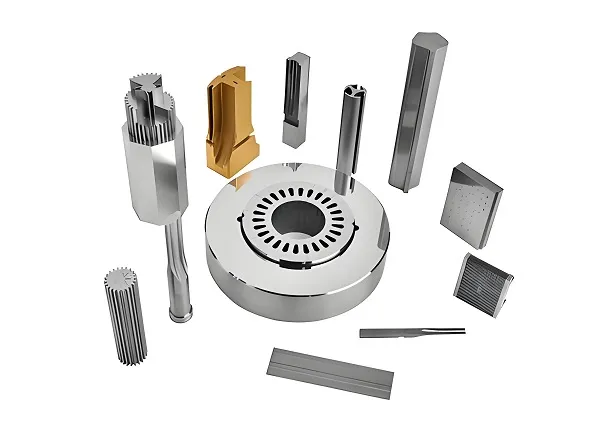
Plastic mold components are precision-engineered parts that work together to form the complete injection molding tooling system. Each component serves a specific function and directly impacts production outcomes.
These components directly influence:
Molding accuracy and dimensional stability
Tool life and wear resistance
Cooling efficiency and cycle time
Final product surface quality
Production throughput and yield
Maintenance cost and downtime
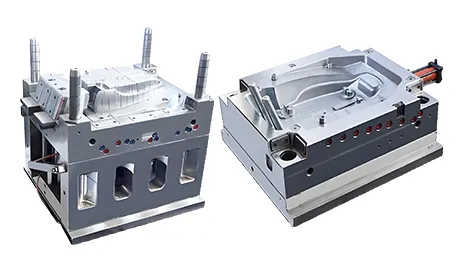
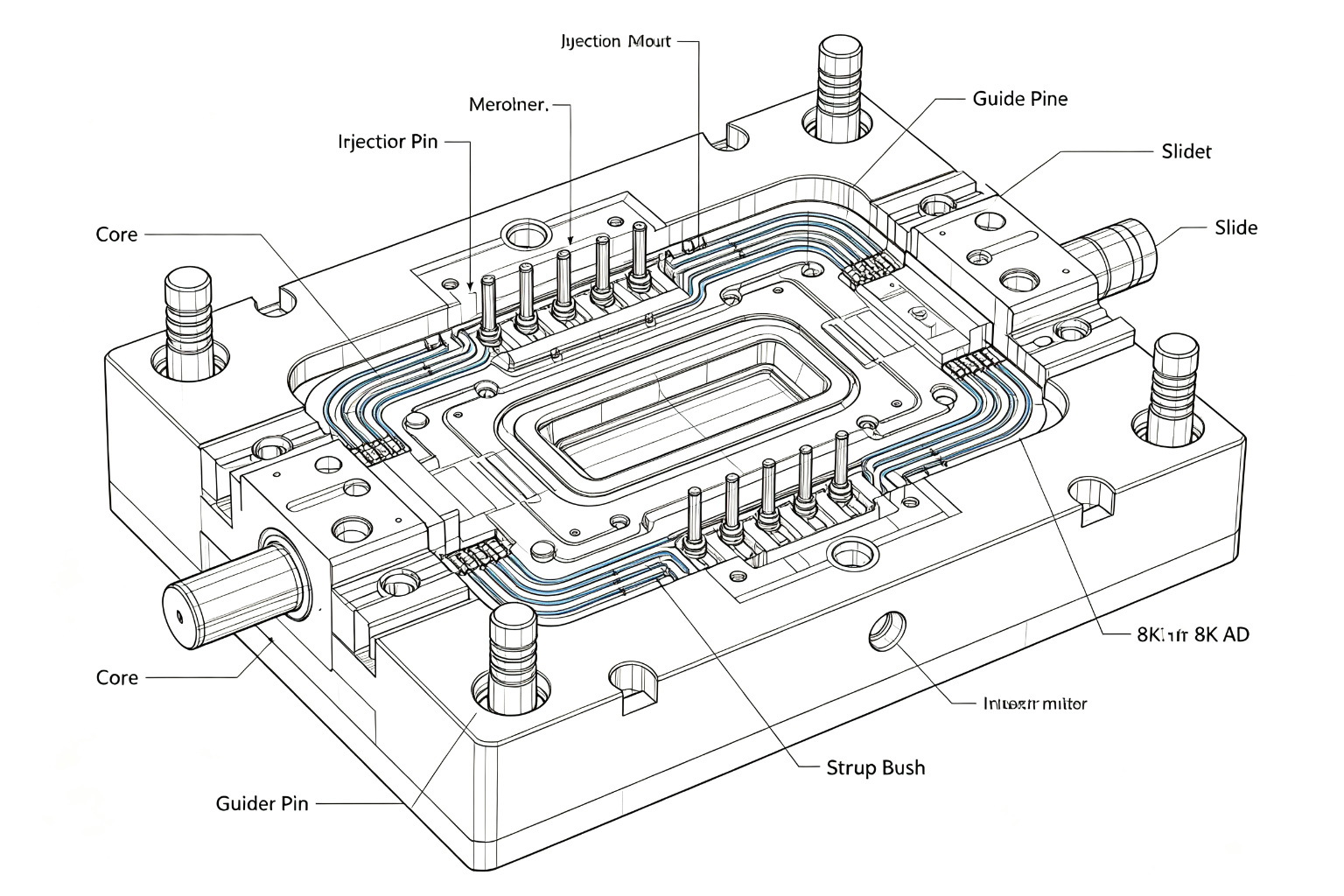
A typical injection mold consists of dozens of individual components, each manufactured to tight tolerances. The most critical parts include the mold base, core, cavity, ejector system, guide pins, sprue bush, runner system, cooling channels, slides, lifters, and interchangeable inserts.
Complete Mold Structure Diagram
Understanding how each component fits within the overall mold assembly helps engineers specify the right materials and tolerances for each application. Below is a cross-sectional view of a standard injection mold.
Engineering Note: The parting line separates the core (moving half) from the cavity (fixed half). Proper alignment between these two halves is maintained by the guide pillar and bush system, typically held to ±0.005mm positional accuracy to prevent flash and ensure part consistency across production runs.
Main Mold Components Explained
Each component in an injection mold serves a specific purpose. Understanding their functions, typical materials, and manufacturing considerations is essential for effective tooling procurement.
Mold Base
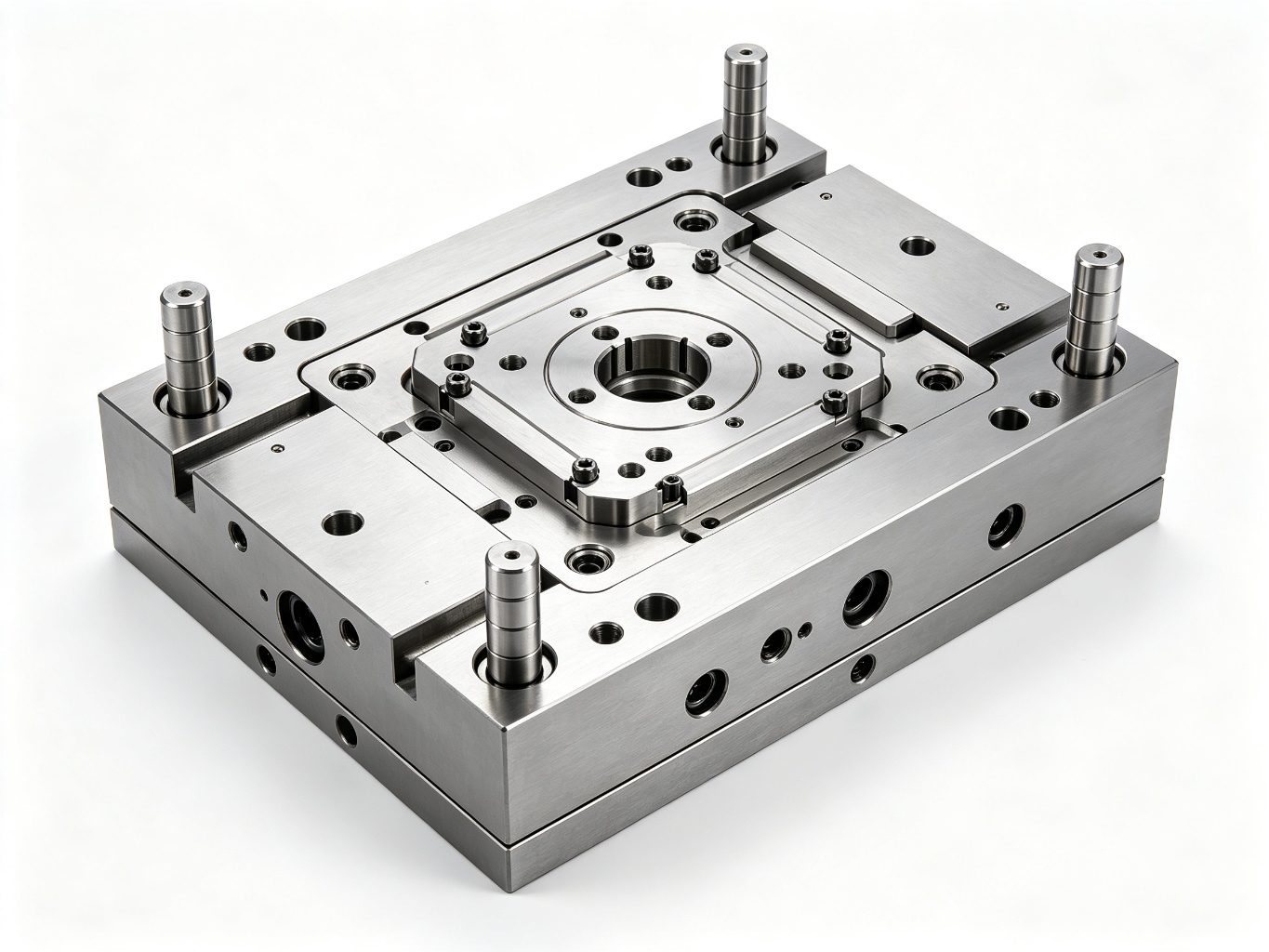
The mold base forms the structural foundation of the entire tooling assembly. It houses all internal components and provides mounting surfaces for the injection molding machine.
Pre-hardened ~30 HRC
Standard / Custom Sizes
Key consideration: Standard mold bases (DME, HASCO, LKM standards) reduce lead time and cost. Custom bases are specified when unusual plate thicknesses or special features are required.
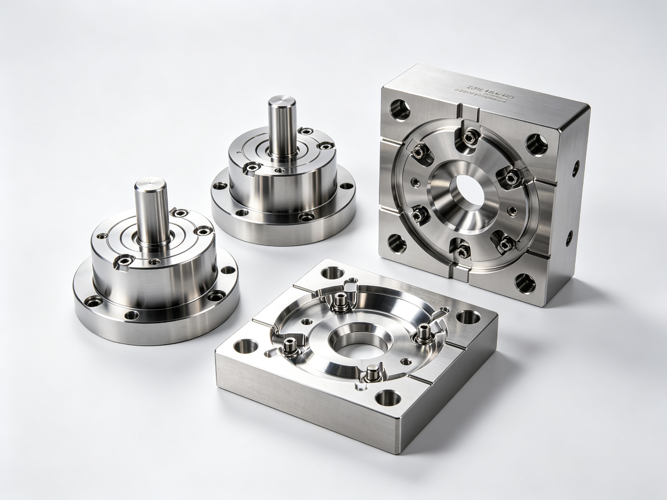
Core & Cavity Inserts
Core and cavity inserts form the actual molding surfaces that shape the plastic part. The cavity creates the exterior surfaces while the core forms interior features.
48-52 HRC Hardened
Mirror Polish Available
Key consideration: Insert-style construction allows for easier replacement of worn or damaged surfaces without rebuilding the entire mold, reducing long-term maintenance costs.
Guide Pillar & Bush
Maintains precise alignment between mold halves during closing. SUJ2 bearing steel, 60 HRC, ground to ±0.002mm roundness.
Critical for flash prevention
Ejector Pin System
Pushes finished parts off the core after molding. SKD61 / H13 steel, 55 HRC, available in standard diameters from 0.8mm to 25mm.
High temperature resistance
Sprue Bush & Locating Ring
Channels molten plastic from the machine nozzle into the runner system. SKD61 steel with hardened wear surfaces.
Standard / Custom Tapers
Slide & Lifter Mechanisms
Creates undercut features that cannot be formed in the straight pull direction. Angle pins or hydraulic actuation options.
For undercut features
Cooling Channels (Bubbler)
Circulates temperature-controlled water to regulate mold temperature. Directly affects cycle time and part warpage.
Cycle time optimization
Hot / Cold Runner Systems
Distributes plastic melt to each cavity. Hot runners eliminate scrap but cost more; cold runners are simpler but generate regrind.
Material cost trade-off
Mold Component Materials Comparison
Selecting the right steel grade for each mold component balances initial cost against expected production volume, required surface finish, and maintenance requirements.
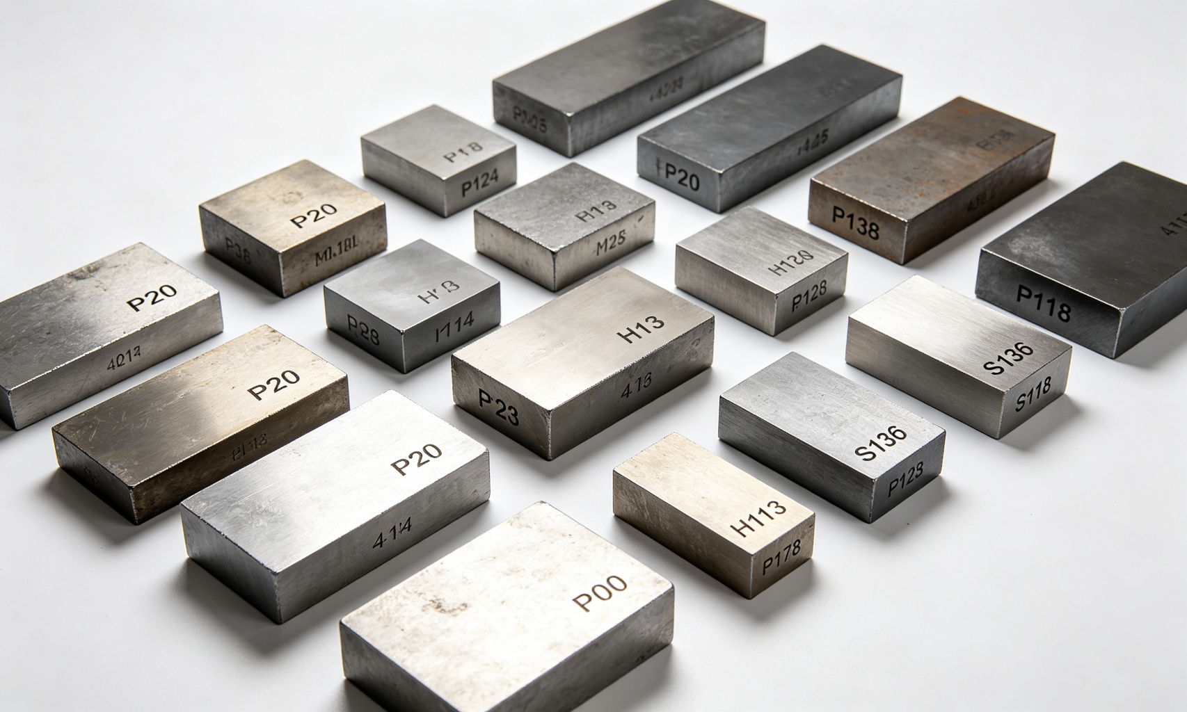
How to Select Mold Component Materials
Material selection should be based on production volume, part geometry complexity, required surface finish, and the plastic material being processed.
Pre-hardened, good for low to medium volume production (under 100k shots). Most economical choice for prototypes and short runs.
Improved P20 variant with higher hardness (35-40 HRC). Better wear resistance for medium volume (100k-500k shots).
Precipitation hardening steel, 40 HRC as-supplied. Excellent polishability for optical and high-gloss applications.
Hot work tool steel, hardened to 48-52 HRC. Best for high-volume production and engineering plastics with elevated melt temperatures.
Stainless tool steel with excellent corrosion resistance. Required for PVC, POM, and other corrosive plastics; also ideal for medical and optical parts.
Exceptional thermal conductivity for difficult-to-cool areas. Used as inserts in hot spots to reduce cycle time and prevent warpage.
| Component | Typical Material | Hardness | Primary Application |
|---|---|---|---|
| Core Insert | H13 / 718H | 48-52 HRC | High wear, high volume |
| Cavity Insert | S136 / NAK80 | 48-50 HRC | Optical / high gloss surfaces |
| Mold Base Plates | P20 / S50C | 28-32 HRC | Structural support |
| Guide Pillar | SUJ2 | 58-62 HRC | Precision alignment |
| Ejector Pin | SKD61 / H13 | 52-56 HRC | High temperature ejection |
| Sprue Bush | SKD61 | 52-55 HRC | Melt channel wear resistance |
Surface Treatments
Surface treatments extend mold life, improve release properties, and enhance part surface quality. The right treatment depends on the plastic material, production volume, and desired finish.
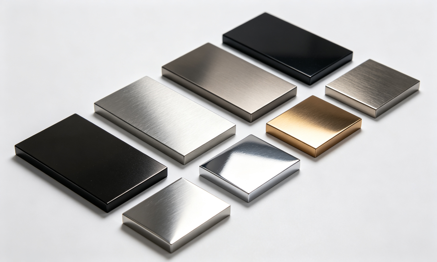
Nitriding
Diffuses nitrogen into the steel surface to create a hard, wear-resistant case (0.3-0.5mm depth). Ideal for high-volume production molds running abrasive glass-filled materials.
DLC (Diamond-Like Carbon)
Ultra-hard coating with excellent release properties. Reduces ejection force and prevents sticking with sticky materials like TPE and soft PVC.
TiN / TiCN Coating
Physical vapor deposition (PVD) coatings that significantly increase surface hardness. Gold-colored TiN is commonly used on ejector pins and slides.
Chrome Plating
Provides corrosion protection and moderate wear resistance. Commonly specified for molds processing corrosive materials like PVC and PET.
Mirror Polish
Achieved through progressive grinding and polishing steps (SPI A-1 to B-3 standards). Required for optical lenses, transparent parts, and high-gloss cosmetic surfaces.
Texture / EDM Finish
Chemical etching or laser texturing creates specified surface patterns (MT, VDI, or custom). Hides weld lines and flow marks on cosmetic parts.
Manufacturing Process Flow
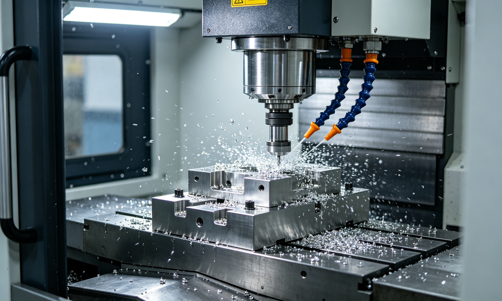
Precision mold components follow a structured manufacturing sequence to ensure dimensional accuracy, material properties, and surface quality meet specification.
→
→
→
→
→
→
→
→
→
→
Quality Note: At Goldcattle, heat treatment is performed after rough machining to relieve internal stresses and achieve uniform hardness throughout the component. This sequence prevents dimensional movement that would occur if machining were performed after hardening. All critical dimensions are verified post-heat-treatment before proceeding to finish operations.
Machining Tolerances & Inspection
Precision mold components require tight tolerances to ensure proper fit, function, and part quality. Different manufacturing processes achieve different levels of accuracy.
Typical Machining Capability
| Process | Typical Accuracy |
|---|---|
| CNC Milling | ±0.01 mm |
| Surface Grinding | ±0.002 mm |
| Sink EDM | ±0.005 mm |
| Wire EDM | ±0.003 mm |
| Cylindrical Grinding | ±0.001 mm |
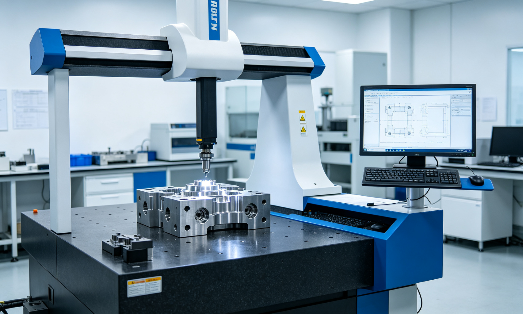
Inspection Equipment
Mold Life & Maintenance
Expected mold life depends heavily on material selection, surface treatment, and proper maintenance. Following a structured maintenance schedule maximizes production uptime and tooling investment.
Expected Mold Life by Material
| Steel Grade | Approx. Shot Life |
|---|---|
| P20 | ~300,000 shots |
| 718H | ~500,000 shots |
| H13 (Hardened) | ~800,000 shots |
| S136 + Nitriding | 1,000,000+ shots |
| H13 + DLC Coating | 1,200,000+ shots |
* Based on standard ABS/PP materials. Glass-filled and abrasive plastics reduce life by 30-50%.
Preventive Maintenance Checklist
🔹 Daily (Every Shift)
- Clean parting surfaces and ejector pins
- Inspect for flash or damage
- Check cooling line flow and temperature
- Lubricate guide pillars and bushes
🔹 Weekly
- Inspect ejector system for wear
- Clean and inspect slide / lifter surfaces
- Verify water lines for blockage
🔹 Monthly
- Full disassembly and deep cleaning
- Check core/cavity surfaces for wear
- Replace worn ejector pins and springs
- Calibrate limit switches and sensors
🔹 Annual / Every 100k Shots
- Complete dimensional inspection (CMM)
- Re-polish and re-treat worn surfaces
- Replace all wear components
- Pressure test cooling system
Common Failures and Solutions
Understanding typical failure modes helps procurement engineers specify the right materials and surface treatments upfront, reducing costly production downtime.
Guide Pin Wear & Galling
Cause: Insufficient lubrication, misalignment, or inadequate hardness.
Solution: Use SUJ2 hardened to 60 HRC with TiN coating. Implement automatic grease lubrication system. Ensure proper press fit installation.
Core Cracking / Fatigue
Cause: Thermal cycling stress, sharp internal corners, or improper heat treatment.
Solution: Use H13 with proper quenching and tempering. Add generous fillets to all internal corners. Consider pre-stressed insert design.
Ejector Pin Sticking
Cause: Pin galling, excessive clearance, or burrs on pin surface.
Solution: Specify SKD61 pins with DLC or TiN coating. Maintain proper fit clearance (0.01-0.02mm). Use guided ejection plates.
Flash on Parting Line
Cause: Worn guide system, parting surface damage, or insufficient clamp force.
Solution: Replace worn guide components. Re-grind parting surfaces. Verify machine tonnage matches projected area.
Cooling Channel Blockage
Cause: Mineral scale buildup, corrosion, or debris accumulation.
Solution: Use treated cooling water. Install inline filters. Implement regular flushing schedule. Consider stainless steel inserts for corrosive environments.
Surface Burn Marks
Cause: Trapped air in cavity causing diesel effect, or inadequate venting.
Solution: Add venting on parting line (0.02-0.03mm depth). Optimize injection speed profile. Ensure proper venting at last-to-fill areas.
Industry Applications
Precision mold components serve diverse industries, each with unique requirements for material specification, tolerance, and surface finish.
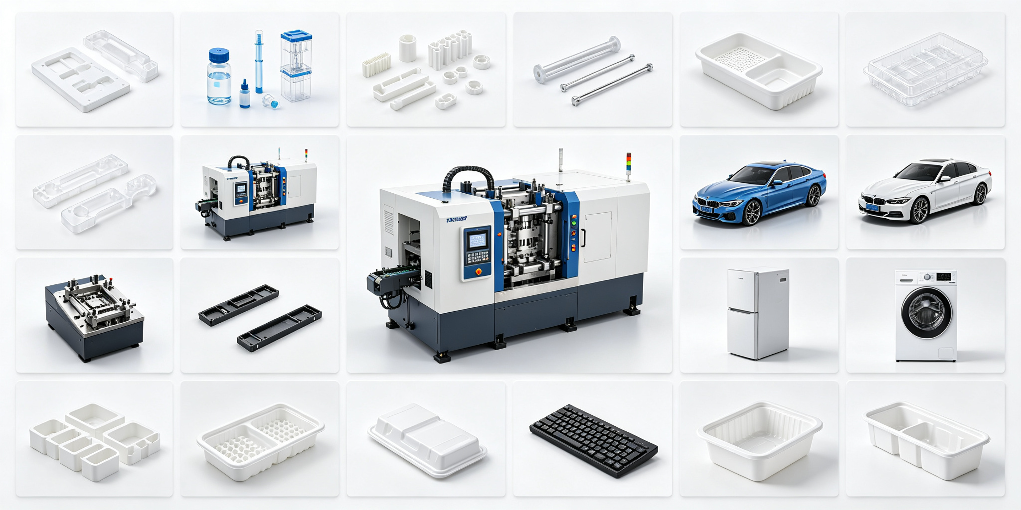
Medical Devices
ISO 13485 compliant, S136 stainless, cleanroom-grade polish
Automotive
IATF 16949, high-volume H13 tooling, PPAP documentation
Electronics
Ultra-precision ±0.005mm, SPI A-2 polish, ESD-safe materials
Home Appliances
Large format tooling, texture finishes, high-cavitation molds
Packaging
High-speed thin-wall tooling, BeCu cooling inserts, 32+ cavities
Aerospace
AS9100 certified, PEKK/PEEK compatible, full material traceability
Industrial
Glass-filled nylon tooling, nitrided surfaces, heavy-duty construction
Consumer Goods
Cosmetic surface textures, multi-color overmolding, rapid tooling
Why Choose Goldcattle for Plastic Mold Components
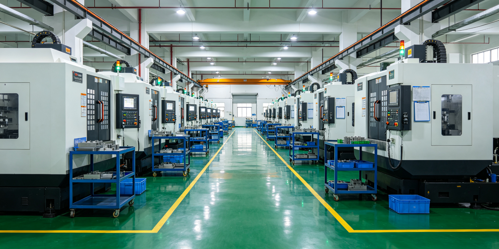
Xiamen Goldcattle Plastic & Metal Products Co., Ltd. specializes in precision mold components and complete injection mold manufacturing for global customers across North America and Europe.
✔
20+ Years of Mold Making Experience
Serving hundreds of international clients with consistent quality and on-time delivery.
✔
Complete In-House Capabilities
5-axis CNC, sink EDM, wire EDM, grinding, polishing, and CMM inspection under one roof.
✔
ISO 9001 & IATF 16949 Certified
Formal quality management system with full material certificates and inspection reports.
✔
DFM Review & Mold Flow Analysis
Free design review before production to identify manufacturability issues and optimize tooling cost.
✔
PPAP & Full Documentation Support
Complete documentation packages including FMEA, control plans, and first article inspection reports.
✔
Global Export Experience
Familiar with DDP shipping, customs clearance, and quality expectations of Western markets.
Automotive Sensor Housing — 30% Cost Reduction
A German automotive Tier-1 supplier approached Goldcattle to re-source a precision sensor housing mold. The original European tooling supplier had a 16-week lead time and high maintenance costs.
Our engineering team optimized the cooling layout using BeCu inserts and recommended S136 stainless steel with nitriding treatment. The mold has been running production for over 18 months with zero unscheduled downtime.
Frequently Asked Questions
Common questions about plastic mold components, materials, and sourcing.
What are plastic mold components?
Plastic mold components are the individual precision parts that make up an injection mold, including the mold base, core, cavity, ejector pins, guide system, and cooling channels. Each serves a specific function in the molding process.
What are mold inserts?
Mold inserts are removable core or cavity blocks that fit into the mold base. They allow for easier replacement of worn surfaces, design changes, and multi-cavity tooling without rebuilding the entire mold structure.
What mold steel material is best?
The best material depends on production volume and plastic type. P20 for low volume, H13 for high volume with engineering plastics, and S136 stainless for corrosive materials or optical-grade surfaces.
How long do mold components last?
Mold life ranges from 300,000 shots for P20 to over 1 million shots for hardened H13 with surface treatments. Glass-filled and abrasive plastics reduce life expectancy by 30-50%.
What is an ejector pin?
An ejector pin is a hardened steel pin that pushes the finished plastic part off the core side of the mold after each cycle. It’s part of the ejection system and must withstand repeated high-temperature operation.
What is the difference between cavity and core?
The cavity forms the outer (A-side) surface of the part, while the core forms the inner (B-side) surface. The cavity is typically on the fixed half of the mold, and the core is on the moving half with the ejection system.
What is a mold base?
A mold base is the standard structural assembly of plates, guide pillars, and ejection mechanism that houses the custom core and cavity inserts. Available in standard sizes (DME, HASCO, LKM) to reduce cost and lead time.
Can mold components be replaced?
Yes, most wear components like ejector pins, guide bushes, and springs are designed to be replaceable. Core and cavity inserts can also be re-machined or replaced if designed with an insert-style construction.
How often should mold components be maintained?
Daily cleaning and lubrication are recommended, with weekly inspection of wear components. Full disassembly and inspection should be performed monthly, or every 50,000-100,000 shots depending on production volume.
What tolerance can CNC machining achieve?
Precision CNC milling typically achieves ±0.01mm tolerance. Grinding can reach ±0.002mm, and wire EDM can hold ±0.003mm. Goldcattle verifies all critical dimensions with CMM inspection.
How do you prevent mold wear?
Prevent wear by selecting appropriate steel hardness, applying surface treatments (nitriding, DLC, TiN), maintaining proper lubrication, and following a preventive maintenance schedule. Proper venting also reduces erosion from gas velocity.
What hardness is recommended for mold components?
Core and cavity inserts should be 48-52 HRC for high-volume production. Guide pillars typically run 58-62 HRC. Ejector pins are 52-56 HRC. Mold base plates are pre-hardened to 28-32 HRC for structural stability.
Can mold components be customized?
Absolutely. Goldcattle manufactures fully custom mold components from your drawings (STEP, IGES, PDF, DWG formats). We also offer DFM review to optimize your design for manufacturability and cost.
How much do custom mold components cost?
Cost depends on material, complexity, tolerance requirements, and quantity. Simple ejector pins start from a few dollars each, while complex 5-axis machined cavity inserts can range from hundreds to thousands of dollars. Contact us for a free quotation.
What is the typical lead time for custom components?
Standard components typically ship in 5-7 business days. Custom machined inserts require 2-3 weeks. Complete mold assemblies take 4-6 weeks depending on complexity. Rush services are available for urgent projects.