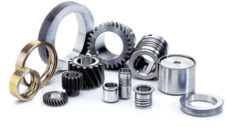
Custom Slide Core Molds for Injection-Molded Parts
Your plastic part has a side hole, groove, or clip that a straight-pull mold cannot release. That is not a problem to redesign around blindly — it is exactly what an angled-pin or hydraulic slide core is built to solve. We design and build the undercut mold, validate it, and run it in series production.
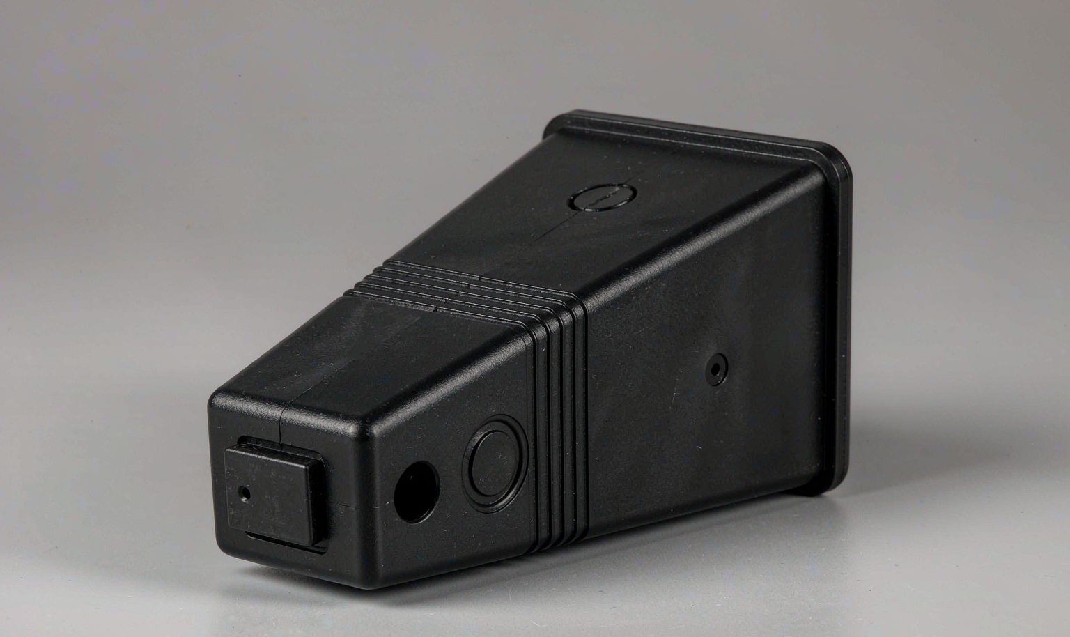
How an Undercut Part Releases: The 5-Step Flow
A straight-pull mold opens along one axis. When a feature blocks that path, the slide core temporarily forms it, then moves out of the way. This is the sequence every slide core mold follows.
When Is a Slide Core Needed?
A slide core becomes necessary the moment a part feature blocks ejection along the mold-open axis. Typical triggers are a side hole through a wall, an external snap or clip, a transverse rib, a boss whose opening faces sideways, or an internal ledge that the cavity would otherwise trap. The quick test: draw the parting line, then imagine lifting the part straight out. Anything that catches is an undercut. The undercut may sit on an outer face, a side wall, or inside a bore. We confirm the undercut type from your 3D model during the DFM review rather than guessing from a 2D drawing.
Slide Core vs Straight-Pull Mold
A straight-pull mold opens in one direction and suits parts whose every feature aligns with that axis. It is cheaper, faster to build, and easier to maintain. A slide core mold adds moving inserts and a guide-lock system so it can form and then clear a side feature. Choose straight-pull whenever the part releases cleanly; add a slide only where the geometry demands it. The decision is not about mold sophistication — it is about whether the plastic can leave the cavity at all. Where the undercut is small and non-functional, we first ask whether it can be moved to the parting line instead of adding mechanism.
Slide Core vs Lifter
Both solve undercuts; they differ by where the undercut lives. A slide core moves sideways and is the right answer for external side walls, side holes, and clip features that open laterally. A lifter is an angled ejector that rises and tilts to strip an internal undercut from the far side of a core — useful when a slide cannot reach into a deep pocket. Slides need clearance beside the cavity; lifters add height below the core and experience higher ejector force. For a combination of internal and external undercuts on one part, a mold may carry both. We specify the motion from the undercut location, not from preference.
How a Slide Core Works
The mechanism follows a fixed sequence inside every cycle:
- The mold closes; the slide core seats against the cavity to form the undercut feature.
- Plastic is injected and packed into the closed cavity.
- The part cools to ejection temperature.
- The mold opens; an angled pin (or cylinder) drives the slide out of the undercut.
- The slide travels clear of the feature by its full undercut depth plus margin.
- Ejectors push the part free, now that nothing blocks the draw path.
Timing matters: the slide must fully retract before ejection, or the part tears.
Slide Drive Options
Three drives cover nearly all undercuts. Angled-pin (cam-pin) slides are linked to the mold-open stroke and need no extra power — ideal for moderate travel and high cycle counts. Hydraulic or cylinder slides hold position independently and suit long travel, heavy undercuts, or features that must stay formed during parting. Combined drives pair a pin with a cylinder for multi-axis or large side features. The choice is driven by travel length, undercut force, and whether the slide must move before or after the mold fully opens.
How Slide Travel Is Determined
Travel is set by geometry, not by a standard value. It equals the deepest undercut dimension plus a clearance margin, usually 2 to 5 mm, so the slide fully clears the feature before ejection. A shallow side rib needs only a few millimeters; a deep transverse boss needs more. We compute travel from the CAD section view and confirm it against the shutoff angle so the slide does not gouge the cavity on retraction. Where space is tight, we reduce travel by reshaping the undercut rather than forcing a longer slide.
Designing Parts for Slide Core
Good undercut parts share a few traits. Give the slide feature enough wall thickness to avoid sink and witness marks. Add draft to the slide-formed face so it releases without drag. Keep the undercut shallow where function allows, and place it where the slide has room to sit beside the cavity. Avoid undercuts that intersect a corner or require the slide to cross a shutoff at a steep angle. Where the feature is cosmetic, set the parting line so any slide witness lands on a non-visible face. These choices cut mold cost and raise yield before steel is cut.
DFM Checklist for Undercut Parts
- Is the undercut real, or can a parting-line move remove it?
- External face → slide; internal far-side → lifter; internal ring/bore → collapsible core.
- What is the true undercut depth, and what travel clears it with margin?
- Is there room beside the cavity for the slide and its guide?
- Shutoff angle 3 to 5 degrees of draft on the mating face?
- Will the material abrade the slide (filled grades → hardened insert)?
- Where does the slide witness land — can it be hidden?
Can a Slide Core Be Avoided?
Often the cheapest mold is the one that does not need a slide. Before quoting mechanism, we look at redesign options that keep function but remove the undercut:
If none of these keep the function, the slide is justified — and we then size it for the longest sensible service life. Redesign advice is part of the review, not a separate charge.
Common Slide Core Problems
| Problem | Typical cause | How we prevent it |
|---|---|---|
| Flash at shutoff | Shallow or worn shutoff angle | 3 to 5 degree draft, ground and CMM-checked faces |
| Slide drag marks | Insufficient draft on slide face | Draft added in design, verified on first article |
| Premature wear | Glass-filled material on soft steel | Hardened inserts at wear surfaces |
| Part tears on eject | Slide not fully retracted | Interlock confirms full travel before ejection |
| Sticking slide | Contamination or no guide clearance | Guided slide with defined lube channel |
| Witness on cosmetic face | Parting line placed visibly | Parting line moved to hidden face |
| Heat build-up | Long cycle, no cooling at slide | Cooling circuit routed through slide where needed |
Long-Run Production Considerations
For high volumes, slide reliability decides mold uptime. We specify hardened inserts at the wear interface, add cooling through the slide where cycle time demands it, and set the guide and lock to hold position for the full planned run. Filled and reinforced grades accelerate wear, so material choice and insert hardness are matched up front. A slide core mold built for a million shots is not the same tool as one built for a few thousand — we size it to your forecast, not to a generic standard.
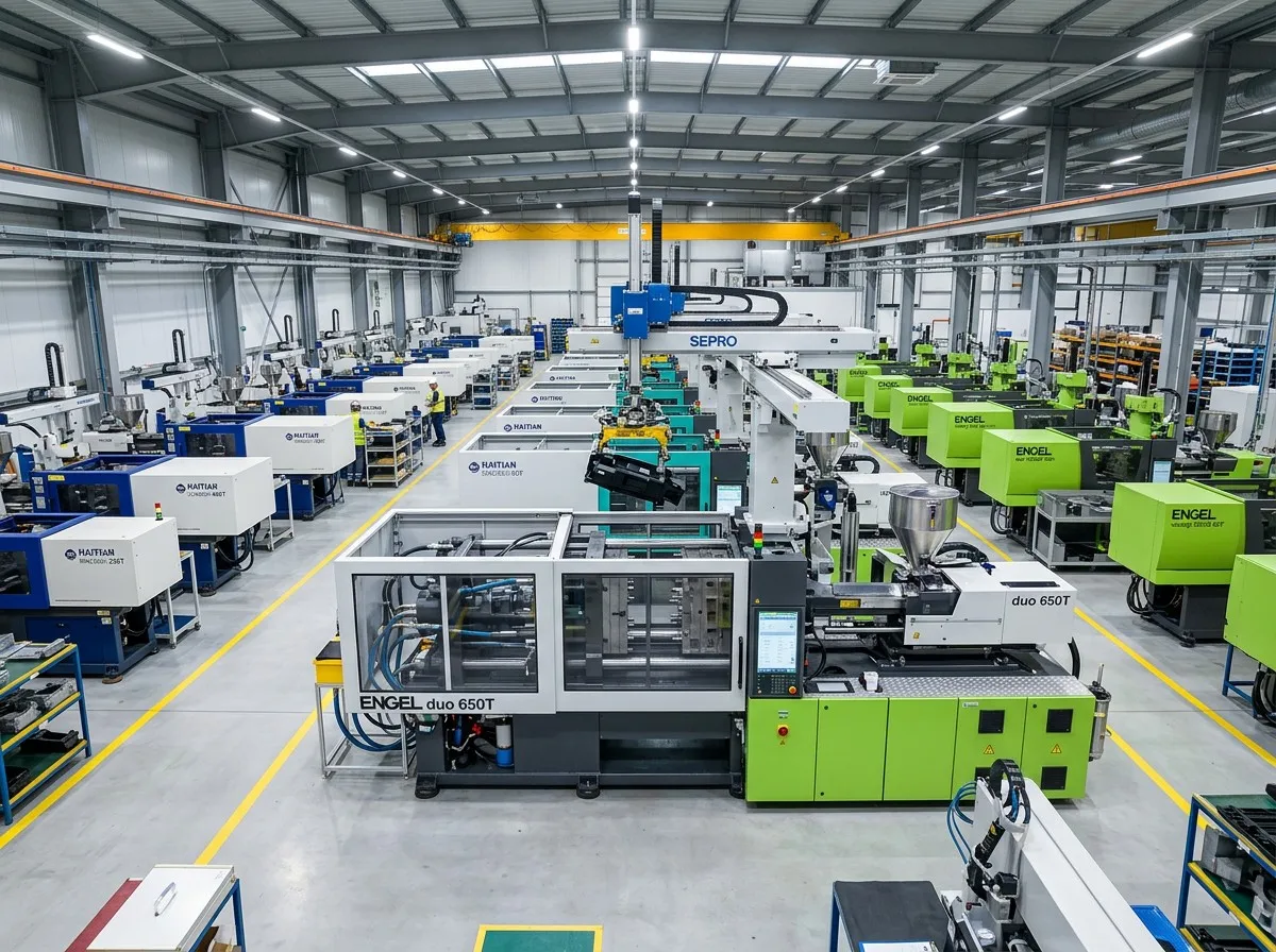
Plastic Materials
Slide cores work across the common thermoplastics. ABS and PC form clean side features and are easy on tooling. PA (nylon) and POM are semi-crystalline and need care on shutoff and wear. PPS and PEEK hold tight tolerances at temperature but are abrasive, calling for hardened slides. TPU and TPE are flexible; their undercuts often release with less travel but need controlled ejection to avoid stretching. We match slide material and finish to the resin so the feature stays crisp across the run.
Mold Steel Selection
Steel is chosen by volume and resin. P20 and 718H (pre-hardened) cover standard and medium runs. H13 resists heat and wear where cycles are long or cooling is aggressive. S136 is used for corrosive or optical grades needing a polished face. For glass-filled or high-abrasion materials, we fit hardened inserts at the slide contact so the base steel can stay economical.
Slide Core vs Collapsible Core
A slide core reaches a side or external undercut by moving sideways. A collapsible core collapses inward to free an internal undercut — a threaded boss, a full internal ring, or a bore a slide cannot enter. Outside undercuts use a slide; inside a closed wall, a collapsible or unscrewing core. Mixing both on one part is normal; selection follows geometry, shown in the tree below.
Undercut Solution Selection
Manufacturing Process
- Review 3D model and flag undercut type during DFM.
- Confirm slide vs lifter vs collapsible core and travel.
- Select mold steel and hardened inserts for the resin.
- Machine cavity, core, and slide to the released design.
- Fit and grind the slide, guide, and locking wedge.
- Assemble the mold and set the slide timing.
- Validate on a trial run with first-article inspection.
- Release to series production once parts are approved.
Mold Validation and First-Article
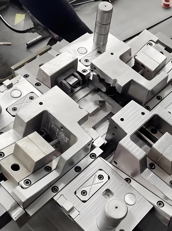
Before any production order, the mold runs a trial. We inspect the first articles for undercut release, shutoff flash, dimensions, and slide witness against your drawing. Critical slide surfaces are checked on the CMM. Only when the parts meet spec do we move to series runs. This step catches timing and shutoff issues while they are still cheap to fix — in steel, not in a customer's shipment.
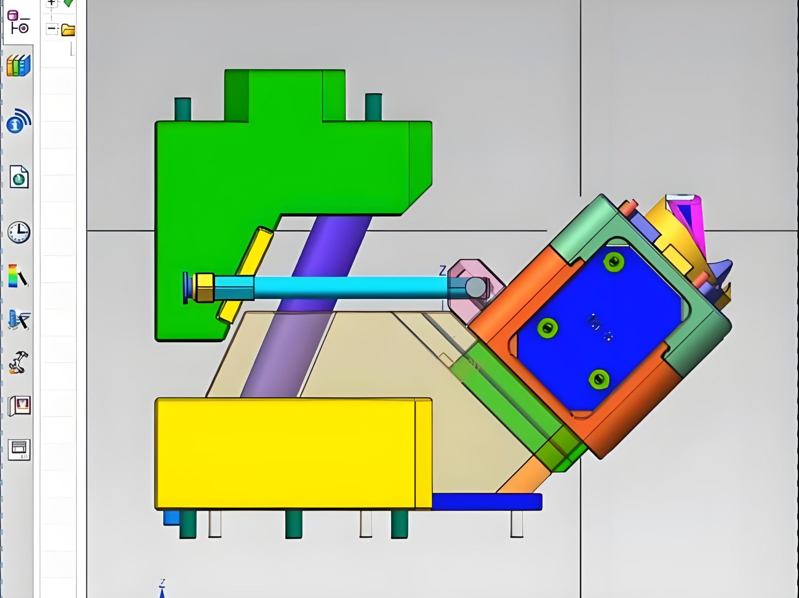
Case Study
The example below is a representative project type we handle. Specific figures are illustrative of a typical slide core program and are not tied to a named customer.
A connector housing needed a transverse side hole that a straight-pull tool could not eject. The original quote assumed a secondary drilling operation after molding. Our DFM review showed the hole could be formed in-shot by a single angled-pin slide. We built the mold with a P20 cavity and a hardened slide insert, validated it on a trial, and released it to production. The result was one molded part instead of two operations, with the side hole held to drawing on every shot. Programs like this are routine for enclosure, connector, and clip features with side undercuts.
Cost Impact of Adding a Slide Core
A slide core raises mold cost and lead time versus a straight-pull tool: it adds machined inserts, a guide and locking system, and extra validation. The offset is that it molds the undercut in one shot instead of adding a post-mold operation such as drilling, routing, or ultrasonic welding. For low volumes the slide may not pay back; for production volumes the single-shot part usually wins on total cost and consistency. We present both paths in the review so the decision is based on your volume, not on a default.
Frequently Asked Questions
See the structured Q&A above for the twelve most common questions on slide cores, drives, travel, materials, steel, flash control, and lead time. If your part raises a question not covered there, send the model and we will answer it in the review.
Request a Slide Core Mold Review
Send your 3D model and volume forecast. We return an undercut assessment, a slide vs lifter vs redesign recommendation, and a dated build-and-validation plan — under one ISO 9001:2015 quality system at Xiamen Goldcattle Plastic & Metal Products Co., Ltd.