Answer
Tolerances for CNC parts typically range from ±0.1 mm to ±0.001 mm (±0.004″ to ±0.00004″), depending on machine precision, material, and application. Standard machining often achieves ±0.1 mm (±0.004″), while precision equipment like 5-axis mills or grinders can reach ±0.01 mm (±0.0004″) or better. Ultra-precision parts (e.g., medical implants) may require ±0.001 mm (±0.00004″), but such tight tolerances significantly increase costs. Factors like material thermal expansion, tool wear, and part complexity also influence achievable tolerances. For example, aluminum parts generally have tighter tolerances than plastics due to lower thermal deformation.
Technical Analysis: CNC Part Tolerances—Factors, Standards, and Control Strategies
1. Tolerance Fundamentals: Definitions and Classifications
- Dimensional Tolerance:Refers to allowable variations in linear dimensions (e.g., length, diameter). Common units: mm or inch.
- Example: A shaft specified as φ10 ±0.05 mm allows diameters from 9.95 mm to 10.05 mm.
- Geometric Tolerance:Controls shape, orientation, or location (e.g., flatness, perpendicularity).
- Example: A part may require a flatness tolerance of 0.02 mm over its entire surface.
- ISO vs. ASME Standards:
- ISO 2768 defines general tolerances (e.g., m-grade for ±0.1 mm, f-grade for ±0.05 mm).
- ASME Y14.5 specifies geometric tolerances using GD&T (Geometric Dimensioning and Tolerancing).
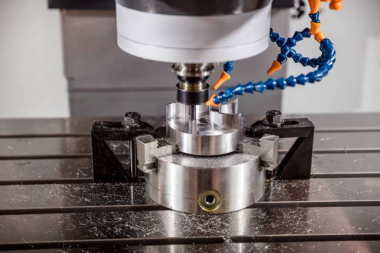
2. Machine Precision: The Core Determinant
- Machine Classifications:
- General-Purpose CNCs (3-axis mills/lathes): Typically achieve ±0.05–0.1 mm (±0.002″–0.004″).
- Precision Machines (5-axis, jig grinders): Capable of ±0.005–0.01 mm (±0.0002″–0.0004″).
- Ultra-Precision Systems (diamond turning): Reach ±0.001 mm (±0.00004″) or better for optics/medical devices.
- Key Components:
- Ball screws (precision grade: ≤0.005 mm/m backlash) and linear guides directly impact positioning accuracy.
- Rotary tables in multi-axis machines must have backlash <0.002° for tight tolerances.
3. Material Impact: Deformation and Machinability
- Metals:
- Aluminum (6061/7075): Good thermal conductivity, allows ±0.02–0.05 mm for small parts.
- Stainless Steel (304/316): Higher work-hardening, may require ±0.05–0.1 mm due to tool wear.
- Titanium (TC4): Low thermal conductivity causes heat buildup, limiting tolerances to ±0.03–0.08 mm.
- Plastics:
- ABS/PC: High thermal expansion (2–10× metal), typical tolerances ±0.1–0.3 mm (±0.004″–0.012″).
- PEEK: Better dimensional stability, allows ±0.05–0.15 mm for precision components.
- Thermal Management:
- Steel parts heated by 10°C expand ~0.012 mm/m, necessitating temperature-controlled workshops (20±1°C) for ±0.01 mm tolerances.
4. Process Selection: Machining Methods vs. Precision
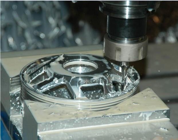
- Milling:
- 3-axis roughing: ±0.1–0.3 mm; 5-axis finishing: ±0.01–0.03 mm.
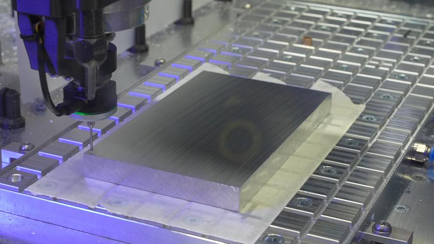
- Example: Milling a 100 mm aluminum plate with 3-axis: ±0.05 mm flatness; 5-axis: ±0.01 mm.
- Turning:
- Conventional lathes: ±0.05–0.1 mm; CNC Swiss lathes: ±0.005–0.01 mm for small diameters.
- Medical pins (φ2 mm) turned on Swiss lathes can achieve ±0.003 mm straightness.
- Grinding:
- Surface grinding: ±0.005–0.01 mm flatness; cylindrical grinding: ±0.002–0.005 mm diameter.
- Bearings races often require ≤0.001 mm roundness via centerless grinding.
- EDM (Electrical Discharge Machining):
- Achieves ±0.005–0.01 mm for hard materials (tungsten carbide), ideal for intricate dies.
5. Industry-Specific Tolerance Standards
| Industry | Typical Tolerance Range | Application Examples |
|---|---|---|
| Automotive | ±0.05–0.2 mm (±0.002″–0.008″) | Engine components, transmission parts |
| Medical | ±0.01–0.05 mm (±0.0004″–0.002″) | Implants, surgical tools |
| Aerospace | ±0.005–0.02 mm (±0.0002″–0.0008″) | Turbine blades, flight control parts |
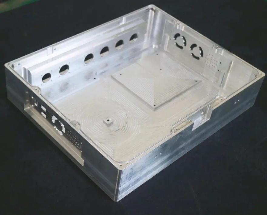
| Electronics | ±0.02–0.1 mm (±0.0008″–0.004″) | Connector housings, heat sinks |
| Consumer Goods | ±0.1–0.5 mm (±0.004″–0.02″) | Phone cases, appliance shells |
6. Tolerance vs. Cost: The Economic Trade-off
- Linear Cost Increase:
- Tightening tolerance from ±0.1 mm to ±0.01 mm can raise costs by 3–5 times due to:
- Longer machining times (slower feeds for precision).
- Higher equipment investment (e.g., 5-axis vs. 3-axis).
- Frequent quality checks (CMM inspections cost $50–$100 per part).
- Tightening tolerance from ±0.1 mm to ±0.01 mm can raise costs by 3–5 times due to:
- Case Study:
- A 50 mm aluminum part with ±0.1 mm tolerance: $15/unit (3-axis milling).
- Same part with ±0.01 mm tolerance: $60–$80/unit (5-axis finishing + CMM).
7. Tolerance Control Techniques
- Process Optimization:
- Roughing + Finishing Stages:Leave 0.5–1 mm stock for finishing to reduce stress-induced deformation.
- Tool Path Strategies:Use climb milling (instead of conventional) for better surface finish (±0.01 mm vs. ±0.03 mm).
- Fixture Design:
- Vacuum chucks for thin-walled parts (e.g., 0.5 mm aluminum sheets) reduce clamping deformation.
- Magnetic fixtures for ferrous materials enable non-marring clamping (±0.005 mm flatness).
- Real-Time Compensation:
- Thermal growth sensors adjust tool paths dynamically (e.g., compensating 0.002 mm/°C for steel).
- AI-driven systems predict tool wear and modify parameters mid-operation (reduces deviation by 40%).
- Post-Processing:
- Heat treatment (e.g., stress relieving) for steel parts to stabilize dimensions (±0.01 mm vs. ±0.05 mm).
- Chemical etching for plastics to remove burrs and achieve ±0.05 mm edge precision.
8. Common Tolerance Pitfalls and Solutions
- Burr Formation:
- Issue: Burrs on edges can exceed ±0.05 mm tolerances.
- Solution: Use deburring tools (e.g., brush deburring for aluminum, ECD for steel) or specify burr-free edges.
- Thermal Expansion:
- Issue: Plastic parts machined at 25°C may shrink by 0.2% at 20°C, causing ±0.1 mm errors in 100 mm parts.
- Solution: Machine at controlled temperature (20±0.5°C) or allow 24-hour thermal equilibration before inspection.
- Multi-Axis Alignment:
- Issue: 5-axis machines with incorrect axis calibration can cause ±0.02 mm positional errors.
- Solution: Perform daily ball bar tests and annual laser calibration (reduces error to <0.005 mm).
Tolerance Verification Methods
- Manual Gauges:Calipers (±0.01 mm), micrometers (±0.001 mm) for simple parts.
- CMM (Coordinate Measuring Machine):Accuracy ±0.001–0.005 mm for complex geometries.
- Laser Scanners:3D scanning with ±0.02–0.05 mm precision for rapid prototyping.
Design Tips for Tolerance Optimization
- Specify Function-Based Tolerances:
- Use loose tolerances (±0.1 mm) for non-critical features; reserve tight tolerances (±0.01 mm) for mating surfaces.
- Follow Standard Tolerance Grades:
- Adopt ISO 2768-m (medium) for general parts or ISO 2768-f (fine) for precision components.
- Avoid Over-Engineering:
- A ±0.05 mm tolerance may suffice for a plastic housing instead of ±0.01 mm, cutting costs by 50%.
In summary, CNC part tolerances are a balance of machine capability, material behavior, process selection, and cost. By aligning tolerance requirements with functional needs and leveraging precision control techniques, manufacturers can achieve optimal quality at reasonable costs.