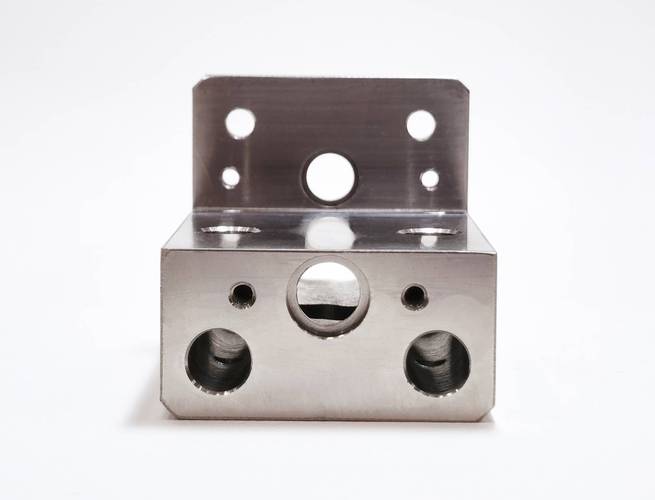
CNC rapid prototype machining (Computer Numerical Control Rapid Prototype Machining) is a technology that uses a computer numerical control system to drive machine tools, transforming 3D CAD models into physical prototypes. By generating processing instructions (G codes) through CAM software, it controls milling machines, lathes, and other equipment to perform subtractive machining such as milling and turning on metals (e.g., aluminum alloy, stainless steel) or engineering plastics (e.g., ABS, nylon), rapidly producing high-precision prototype parts. Its core advantages lie in high machining accuracy (within ±0.05mm) and material properties close to finished products. It is commonly used in the product development stage to verify design feasibility, conduct functional tests, and assemble verification, efficiently realizing the transformation from digital models to physical parts, especially suitable for manufacturing prototypes with complex structures and high-precision requirements.
I. Technical Core and CNC Principles
1. Digital Control Technology
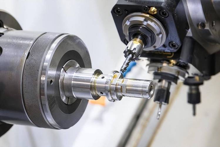
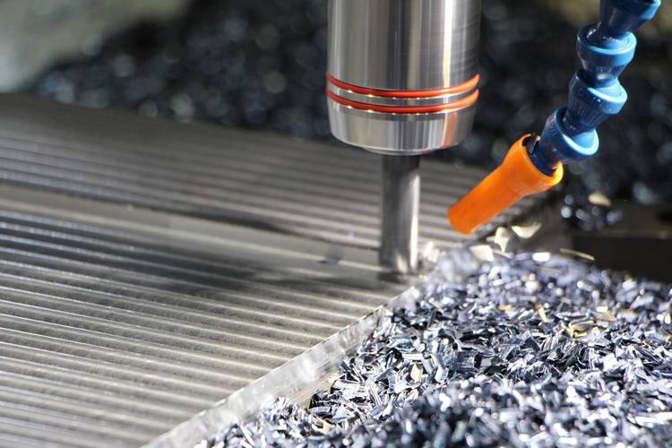
The essence of CNC technology is to precisely control the movement trajectory of machine tools through computer programs (G codes/M codes), achieving the transformation of “digital model→physical parts”. Taking a three-axis machining center as an example, the servo motors of the X/Y/Z axes move synchronously according to instructions to drive the tool for linear and arc cutting, while a five-axis machine adds A/C rotating axes to achieve multi-angle inclined machining, competent for complex curved surface parts such as impellers and turbines.
The essence of CNC technology is to precisely control the movement trajectory of machine tools through computer programs (G codes/M codes), achieving the transformation of “digital model→physical parts”. Taking a three-axis machining center as an example, the servo motors of the X/Y/Z axes move synchronously according to instructions to drive the tool for linear and arc cutting, while a five-axis machine adds A/C rotating axes to achieve multi-angle inclined machining, competent for complex curved surface parts such as impellers and turbines.
2. Technical Differences from Traditional Machining
- Automation Level: Traditional machine tools rely on manual operation, while CNC is completely controlled by programs, with a repeatability accuracy of 0.01mm, suitable for batch prototype manufacturing.
- Flexible Manufacturing: When changing processing tasks, only the program needs to be modified without readjusting the mechanical structure, improving production efficiency by 3-5 times compared with special tooling and molds.
II. Analysis of the Full Process
1. Prototype Process Planning
- Model Preprocessing: Use Geomagic to repair broken surfaces of CAD models and conduct machinability analysis through Hypermill. For example, split Undercut structures (undercuts) into upper and lower parts to avoid tool interference.
- Clamping Scheme: Use a vise to clamp small parts and design special fixtures for large metal parts to ensure sufficient rigidity during machining (e.g., four-point support for automotive panel prototypes).
2. Execution of Cutting Processes
- Rough Machining: Adopt a large-diameter end mill (e.g., φ20mm) to quickly remove materials with a “peripheral milling” strategy, with a cutting depth of 2-5mm and a feed rate of 800-1200mm/min.
- Finishing Machining: Switch to a ball-end mill (e.g., φ4mm) for surface milling, leaving a margin of 0.1-0.3mm, and control the surface roughness Ra ≤ 1.6μm through “contour milling”.
3. Typical Process Case
When machining a medical endoscope housing prototype, first remove 90% of the aluminum alloy material by rough milling, then use a five-axis machine to process a φ1.5mm through-hole and a 45° inclined observation window surface, and finally perform electrochemical polishing to make the inner wall surface roughness reach Ra 0.4μm.
When machining a medical endoscope housing prototype, first remove 90% of the aluminum alloy material by rough milling, then use a five-axis machine to process a φ1.5mm through-hole and a 45° inclined observation window surface, and finally perform electrochemical polishing to make the inner wall surface roughness reach Ra 0.4μm.
III. Technical Terms and Concepts
| Term | Definition and Application Scenario |
|---|---|
| Tool Path | The tool movement trajectory generated by CAM software, such as “helical milling” for hole machining and “radial milling” for arc surfaces. |
| Cutting Parameters | Include spindle speed (rpm), feed rate (mm/min), and cutting depth. For example, when machining stainless steel, the speed should be controlled at 1500-2500rpm to prevent tool wear. |
| G Code | The core instruction of NC programs, such as G01 linear interpolation, G02 clockwise arc, and G41 left tool offset for compensating tool radius. |
| Tolerance Fit | The allowable dimensional error of prototype parts. For example, shaft-hole fit needs to be controlled at H7/g6 (clearance fit) to ensure assembly accuracy. |
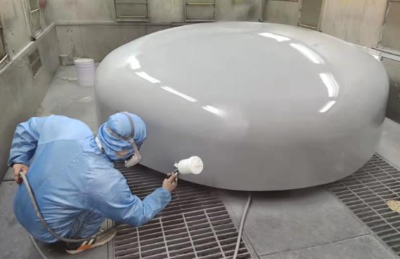
| Post-Processing | Including deburring (electrolytic deburring for precision parts) and surface hardening (nitriding to improve the hardness of metal prototypes). |
IV. Machining Capabilities and Part Characteristics
1. Adaptability to Part Structures
- Complex Structure Machining: Five-axis machines can machine the twisted profiles of aero-engine blades. Through “side milling”, tool interference with parts is avoided, and the minimum machining fillet radius reaches 0.2mm.
- Thin-Wall Part Machining: Adopt the process of “layered cutting + elastic support”. When machining a plastic shell with a wall thickness of 0.5mm, reduce vibration deformation by decreasing the feed speed (300mm/min).
2. Materials and Part Properties
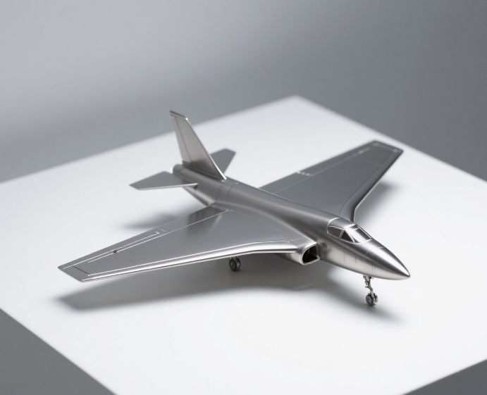
- Metal Parts: Aluminum alloy 6061 prototypes have a tensile strength of 310MPa and can be directly used for functional tests of automotive steering knuckles; titanium alloy Ti-6Al-4V prototypes are suitable for aviation lightweight components.
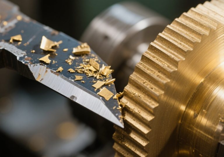
- Plastic Parts: Nylon PA6 prototypes with glass fiber reinforcement have a bending strength of 100MPa, suitable for making wear-resistant test parts such as gears and bearings.
V. Part Verification and Application Scenarios
1. Functional Verification
- Moving Component Testing: CNC-machined gear prototypes need to undergo a running-in test to verify tooth surface contact accuracy, with the fit clearance controlled at 0.03-0.05mm to simulate actual working conditions.
- Hydrodynamic Testing: Water pump impeller prototypes need to undergo a hydrostatic test. The smooth flow channel (surface roughness Ra ≤ 0.8μm) machined by CNC reduces hydraulic loss.
2. Typical Parts in Industries
- Automotive Field: Engine block prototypes (needing to machine φ80mm cylinder bores with cylindricity ≤ 0.02mm) and instrument panel housings (assembly hole positional tolerance ≤ 0.1mm).
- Electronic Field: 5G base station heat sink fin prototypes (thickness 0.8mm, perpendicularity ≤ 0.05mm), ensuring heat dissipation efficiency through CNC milling.
Conclusion
CNC rapid prototype machining, with CNC technology at its core, achieves rapid manufacturing of high-precision parts through precise process planning and cutting control. From G code control in technical principles to rough and finish milling in processes, and then to material properties and functional verification of parts, its full-chain capabilities support the “design-verification-optimization” iteration process in product development, especially playing an irreplaceable role in high-precision fields such as aerospace and medical care.