Aluminum CNC Machining Best Practices for Precision Manufacturing
As part of our comprehensive CNC machining services, Goldcattle provides custom aluminum machining for prototype and production applications, with precision milling and turning capabilities to deliver lightweight, high-performance parts.
- ✓ Custom 3/4/5-axis aluminum machining
- ✓ Full range of aluminum grade support
- ✓ Prototype to mass production
- ✓ Complete surface finishing options
Why Is Aluminum Popular in CNC Machining?
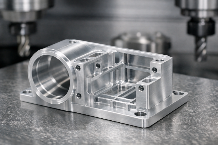
Aluminum is one of the most widely machined metals in modern manufacturing, thanks to its exceptional combination of physical and mechanical properties that make it ideal for precision CNC processing.
Compared with harder metals like steel, aluminum offers unique advantages for machining:
- • Faster machining speeds that reduce production time
- • Reduced tool wear that lowers long-term production costs
- • Excellent chip evacuation that simplifies processing
- • Superior surface finishing capabilities for aesthetic parts
- • Outstanding strength-to-weight ratio for lightweight components
These characteristics make aluminum the material of choice for aerospace, automotive, electronics, and industrial applications where performance and efficiency are critical.
Common Aluminum Grades for CNC Machining
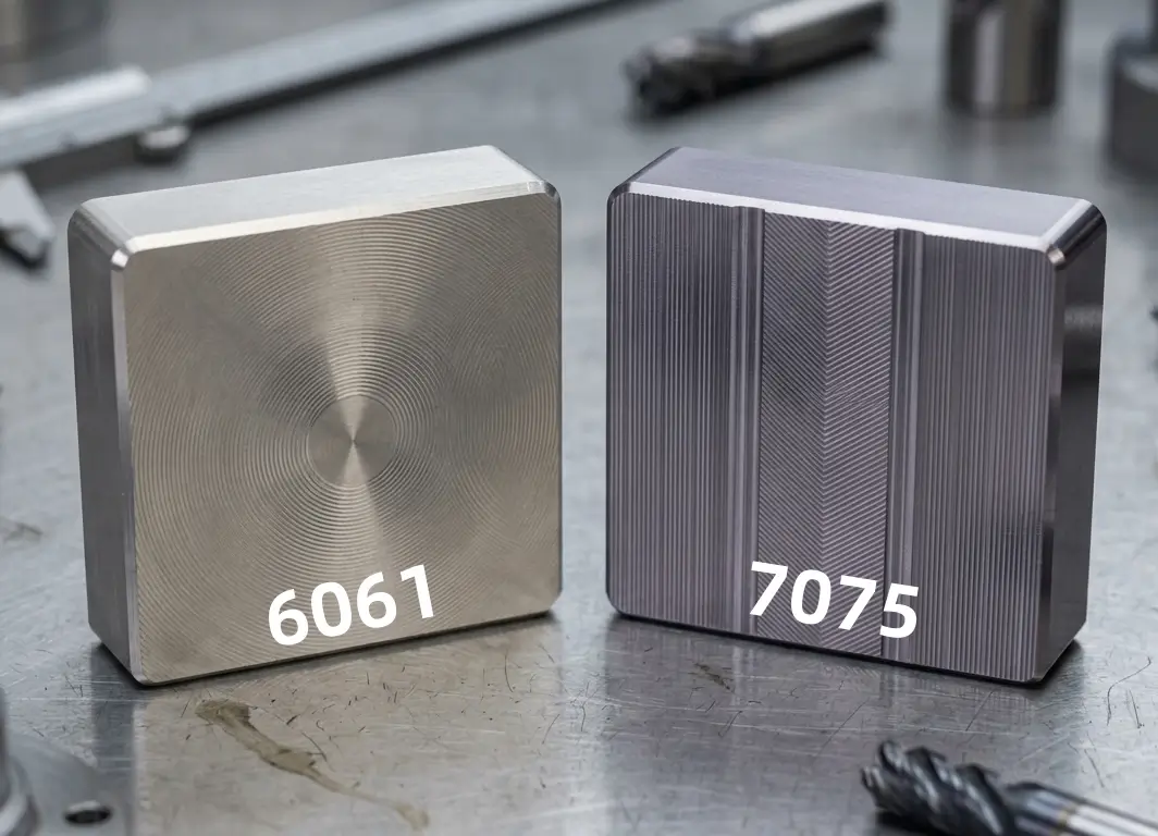
6061 Aluminum
The most versatile general-purpose aluminum alloy, offering excellent corrosion resistance, good weldability, and strong machinability at an economical price point.
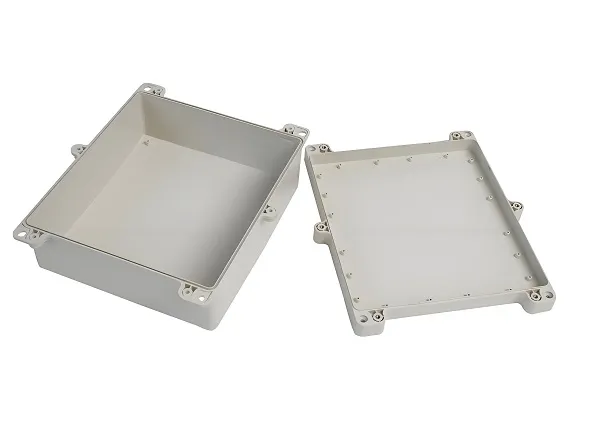
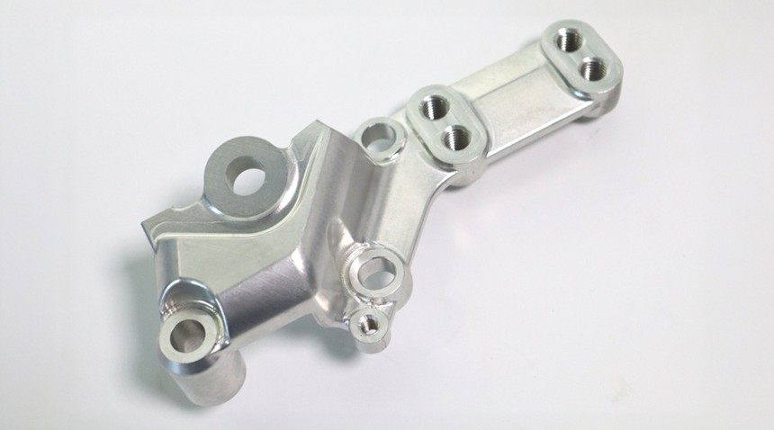
Typical applications: General structural parts, brackets, enclosures, and components requiring moderate strength.
7075 Aluminum
High-strength aerospace-grade aluminum, with strength comparable to many steels while maintaining lightweight properties. It offers excellent fatigue resistance for demanding applications.
Typical applications: Aerospace structural parts, high-stress components, and military equipment.
5052 Aluminum
Sheet-friendly alloy with excellent corrosion resistance, particularly in marine environments. It has good formability and work-hardening characteristics.
Typical applications: Sheet metal parts, heat sinks, marine components, and general sheet fabrication.
2024 Aluminum
High-strength alloy with excellent fatigue resistance, ideal for applications subject to repeated stress and load cycles.
Typical applications: Aircraft structural components, aerospace fittings, and high-stress mechanical parts.
Best Practices for Aluminum CNC Machining
Achieving optimal results in aluminum machining requires specialized process control to address the unique properties of the material.
Tool Selection
We use sharp carbide tools with polished flutes to prevent built-up edge, ensuring clean cuts and reducing the risk of material adhesion to the cutting tool.
Cutting Parameters
Optimized spindle speeds and feed rates leverage aluminum’s machinability, allowing faster material removal while maintaining dimensional stability and surface quality.
Chip Evacuation
Proper chip removal prevents recutting of aluminum chips, which can cause surface scratching and dimensional errors, particularly in deep pocket machining.
Coolant & Lubrication
Specialized coolant solutions manage thermal expansion during machining, preventing dimensional drift and protecting surface finish from heat-related damage.
Fixture Design
Rigid fixturing and proper clamping force prevent thin-wall deformation, ensuring that even the most delicate aluminum components maintain their shape during processing.
Heat Management
Controlled material removal rates prevent excessive heat buildup that could cause thermal deformation, particularly for large or thin-walled aluminum parts.
Common Challenges in Aluminum CNC Machining
While aluminum is highly machinable, it presents unique challenges that require specialized process knowledge to overcome.
Burr Formation
Aluminum’s ductility can lead to edge burrs, which we control through optimized tool geometry and secondary deburring processes.
Built-Up Edge
Material adhesion to cutting tools is prevented through sharp tooling and proper lubrication, ensuring consistent cutting performance.
Thermal Deformation
Aluminum’s high thermal expansion coefficient is managed through controlled cooling and process monitoring to maintain tolerance.
Vibration & Chatter
Rigid machine setup and optimized cutting parameters prevent vibration marks that could compromise surface finish quality.
Surface Scratching
Careful part handling and chip management prevent surface damage during and after the machining process.
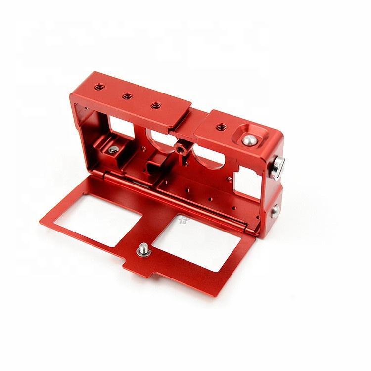
Surface Finishing for Aluminum CNC Parts
Aluminum’s versatility extends to a wide range of surface finishing options, allowing you to achieve the exact appearance, corrosion resistance, and functional properties your project requires.
Anodizing
The most popular finishing option, anodizing creates a protective oxide layer that improves corrosion resistance, increases surface hardness, and allows for custom color options ranging from clear to vibrant colors.
Sandblasting
Creates a uniform matte finish, hiding machining marks and providing a consistent, non-reflective surface ideal for industrial or aesthetic applications.
Polishing
Produces a high-gloss, mirror-like surface finish, perfect for consumer products, decorative components, and parts requiring a premium appearance.
Powder Coating
Provides a durable, protective coating with excellent scratch and corrosion resistance, available in a wide range of colors and finishes for industrial and consumer products.
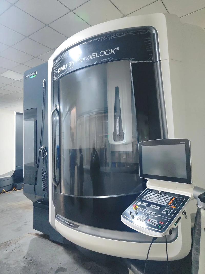
Our Aluminum CNC Machining Capabilities
As an experienced aluminum CNC manufacturer, we have the equipment and expertise to handle projects of all sizes, from initial prototypes to full-scale production runs.
Supported Materials
7075-T6
5052-H32
2024-T3
6063
Processes
Specifications
- • Material thickness: 0.5mm – 100mm
- • Standard tolerance: ±0.01mm
- • Production volume: 1 – 100,000+ parts
- • Maximum part size: 1000mm x 800mm
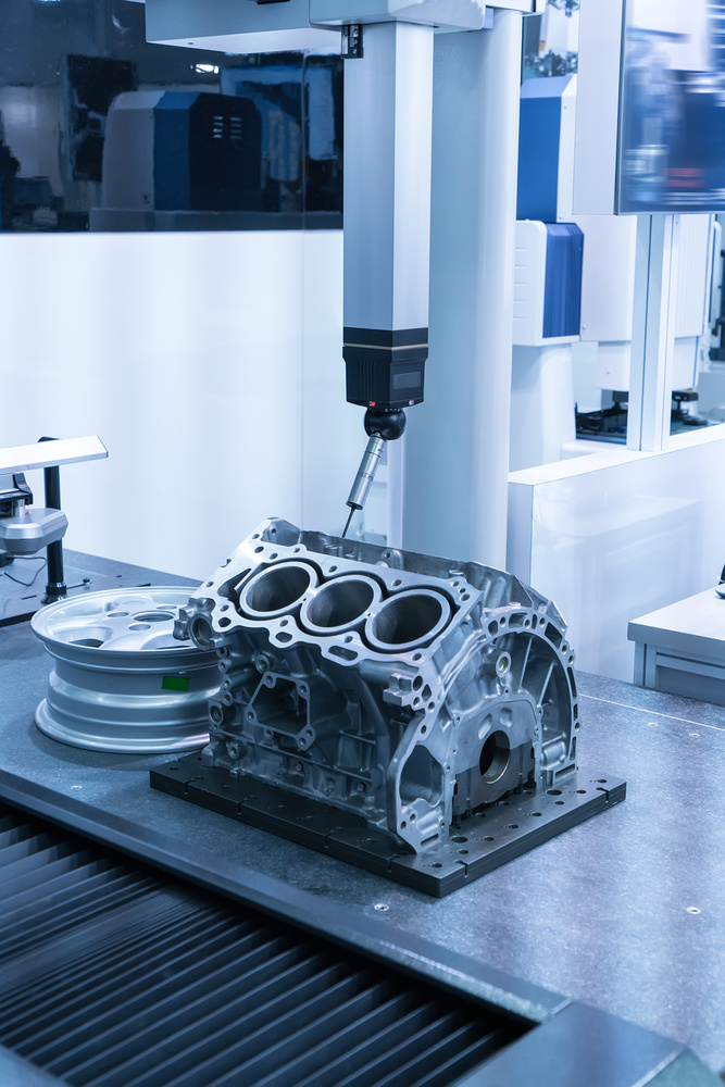
Quality Control for Aluminum Machining
Maintaining precision in aluminum machining requires rigorous process control and inspection to account for the material’s unique properties. We implement comprehensive quality measures to ensure every part meets your exact specifications.
- ✓ First Article Inspection (FAI) for every new production run
- ✓ In-process dimensional checks to catch deformation early
- ✓ CMM coordinate measuring for critical dimensions
- ✓ Raw material certification and incoming inspection
- ✓ Final surface quality and burr inspection
Frequently Asked Questions
Which aluminum grade is best for CNC machining?
6061 aluminum is generally the best all-around choice for most CNC machining projects, offering excellent machinability, corrosion resistance, and cost-effectiveness. For applications requiring higher strength, 7075 is the preferred option, though it is slightly more difficult to machine.
Is 6061 or 7075 easier to machine?
6061 aluminum is generally easier to machine than 7075. It produces cleaner cuts, less tool wear, and fewer burrs, making it ideal for most general-purpose parts. 7075 requires slightly more careful process control due to its higher strength.
What tolerance can aluminum CNC machining achieve?
Our standard aluminum CNC machining can achieve tolerances as tight as ±0.01mm for most parts, depending on the size and complexity. For less critical features, we can maintain standard commercial tolerances that balance cost and performance.
How do you prevent burrs in aluminum machining?
We prevent burrs through a combination of sharp cutting tools, optimized feed and speed parameters, and specialized tool geometry. We also perform secondary deburring operations to remove any remaining burrs and ensure clean, smooth edges on every part.
Does aluminum require coolant during CNC machining?
Yes, coolant is typically required for aluminum CNC machining. It helps manage heat buildup to prevent thermal deformation, improves chip evacuation, and prevents built-up edge on cutting tools, ensuring better surface finish and longer tool life.
What surface finish options are available for aluminum parts?
We offer a full range of surface finishing options for aluminum parts, including anodizing, sandblasting, polishing, powder coating, and more. Each option provides different benefits in terms of appearance, corrosion resistance, and surface hardness to match your project needs.
Ready to Start Your Aluminum CNC Machining Project?
Whether you need prototype parts for product development or high-volume production of precision aluminum components, we have the technical expertise to deliver consistent quality at competitive prices.