
What Is Plastic Injection Molding? How It Works, Materials & Applications
A complete introduction to plastic injection molding — the process, materials, mold components, design considerations, common defects and how to decide whether injection molding is the right manufacturing method for your part.
Plastic injection molding is a manufacturing process in which plastic resin is heated, plasticized and injected into a mold cavity under pressure. The material then cools and solidifies into the required part geometry.
The process is especially suited to repeatable production of plastic components because one mold can produce many consistent parts once the tooling and process are validated.
01How Does Plastic Injection Molding Work?
The injection molding cycle consists of sequential phases, each controlled by machine parameters that affect part quality, cycle time and tool life.
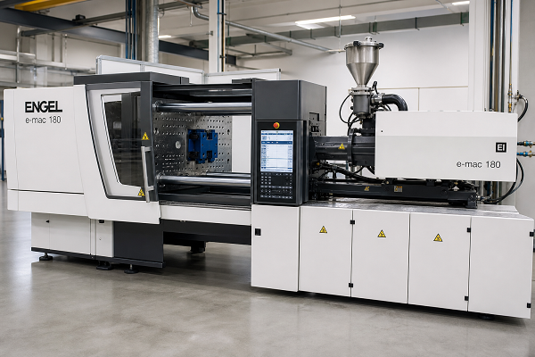
A Repeating Cycle
Injection molding is a cyclic process. The machine clamps the mold, injects molten plastic, holds pressure while the part cools, opens the mold and ejects the part — then repeats. A typical cycle for a small part may take 10–30 seconds; larger or thicker parts require longer cooling times.
Resin Preparation
Plastic pellets are prepared according to the material requirements. This typically includes drying hygroscopic resins to the supplier-specified moisture level, blending with colorants or additives, and feeding into the machine hopper.
Plasticizing
The rotating screw draws resin from the hopper into the barrel. As the material moves forward, it is heated by both external barrel heaters and internal shear friction. The combined heat and shear transform the solid pellets into a homogeneous melt.
Mold Clamping
The machine closes the mold and applies clamping force to resist the injection pressure. Clamping force must exceed the projected area of the cavity multiplied by the peak injection pressure, or the mold will flash at the parting line.
Injection
The screw moves forward and pushes the molten plastic through the nozzle into the gating system: sprue, runner, gate and cavity. Injection speed and pressure are critical — too slow causes short shots or flow marks; too fast can cause flash, jetting or burn marks.
Packing / Holding
After the cavity is filled, holding pressure is maintained to compensate for volumetric shrinkage as the plastic cools and contracts. This phase directly affects sink marks, part dimensions and part weight. Insufficient hold pressure leads to shrinkage defects; excessive pressure can cause flash.
Cooling
The plastic solidifies inside the mold while coolant circulates through the mold's cooling channels. Cooling time can represent a significant portion of the total molding cycle, especially for thick-walled parts. Efficient cooling channel design is one of the most important factors in cycle time and part quality.
Mold Opening & Ejection
The machine opens the mold. Ejector pins, stripper plates or robotic systems remove the part from the core side. Proper draft angles and ejection design prevent part damage, ejector marks and sticking.
Inspection & Secondary Operations
Ejected parts are inspected for appearance and dimensions. Secondary operations may include trimming gates and runners, deburring, assembly, surface finishing or decoration. The cycle then repeats.
02What Does the Injection Mold Do?
The mold defines the part geometry, controls material flow, manages cooling and enables part removal. Each component serves a specific function.
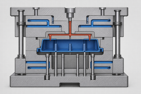
Precision Tooling
An injection mold is a precision tool typically machined from hardened tool steel (P20, H13, S136 or equivalent). It must withstand thousands of injection cycles at high temperature and pressure while maintaining dimensional accuracy. Mold design and construction are covered in detail on our Custom Plastic Injection Mold page.
Cavity
Defines the external geometry and surface finish of the molded part. The cavity side typically forms the visible "A" surface.
Core
Forms the internal features of the part. The core side typically contains the ejection system and is the side from which the part is removed.
Runner System
Distributes molten plastic from the sprue to each gate. Cold runner systems are most common; hot runner systems reduce waste by keeping the melt in a heated manifold.
Gate
The entry point where molten plastic flows from the runner into the cavity. Gate type, size and location affect filling behavior, weld line position, appearance and dimensional stability.
Cooling Channels
Channels in the mold through which temperature-controlled water or oil flows. Cooling channel layout directly affects cycle time, part warpage and dimensional consistency.
Ejection System
Ejector pins, sleeves or stripper plates that push the part off the core when the mold opens. Ejection must be balanced to avoid part deformation or ejector marks.
03What Plastics Can Be Injection Molded?
Most thermoplastics can be injection molded. Material selection depends on the mechanical, thermal, chemical, regulatory and appearance requirements of the part.
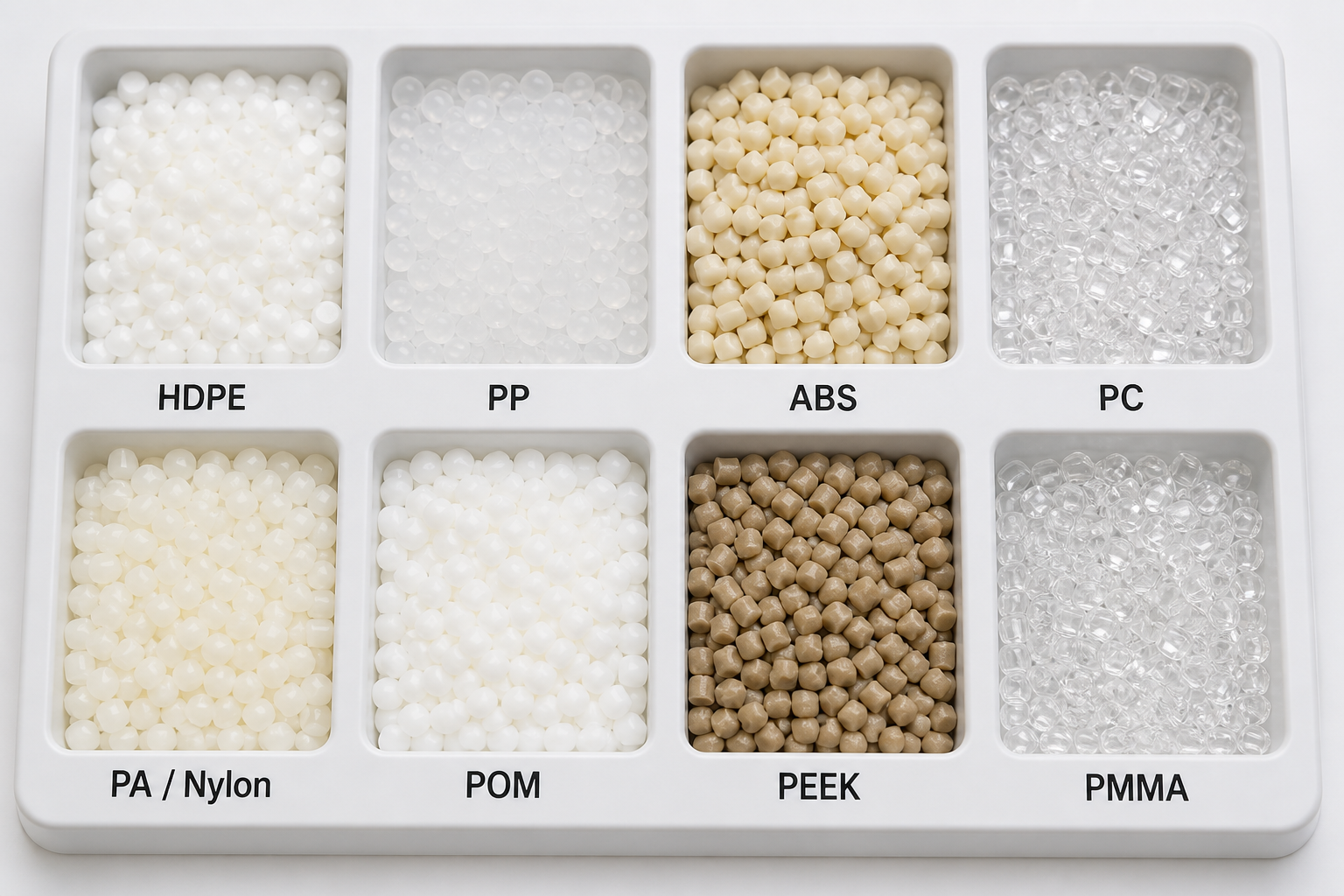
04How to Choose the Right Injection Molding Material
Material selection should follow the actual mechanical, thermal, chemical, regulatory and dimensional requirements of the part — not just the material name.
ABS material properties, processing guidelines and application examples.
05Why Use Plastic Injection Molding?
Injection molding offers specific advantages that make it the preferred process for certain types of production.
Repeatability
Once a mold is built and the process validated, each cycle produces a part with consistent geometry, dimensions and appearance. This is critical for quality-controlled production runs.
Complex Geometry
Injection molding can form features that would be difficult or expensive to machine: ribs, bosses, snap fits, thin walls, living hinges and integrated features — all in a single molding operation.
Volume Economics
Mold tooling has a high upfront cost, but as production quantity increases, the per-part cost typically decreases. For medium to high volumes, injection molding often becomes the most cost-effective option.
Multi-Material Capability
Insert molding and overmolding allow combining different materials or incorporating metal inserts in a single part. This enables integrated assemblies that would otherwise require separate components and joining operations.
Two-shot and overmolding for multi-material plastic components.
06When Is Injection Molding the Right Manufacturing Process?
Injection molding is not always the best choice. The decision depends on volume, geometry, material, tolerance and budget.
Injection Molding Is Typically Suitable When:
- Repeat production of identical parts is needed
- Medium to high volumes justify tooling investment
- Part geometry includes complex molded features
- Consistent appearance and dimensions are required
- Integrated features (snap fits, bosses, living hinges) are needed
- Multi-material or insert molding is desired
Other Processes May Be Better When:
- Only 1–10 prototypes are needed
- Design is still rapidly changing
- Very low production quantities are required
- No tooling budget is available
- Part geometry is better suited to subtractive or additive methods
- Metal parts are required (CNC machining may be preferred)
07Injection Molding vs CNC Machining vs 3D Printing
Understanding the trade-offs between these three processes helps you select the right manufacturing route.
| Factor | Injection Molding | CNC Machining | 3D Printing |
|---|---|---|---|
| Tooling Required | Yes — injection mold | No dedicated mold | No |
| Best Volume | Medium to high | Low to medium | Prototype / low volume |
| Geometry | Complex molded features | Excellent for subtractive features | Highly complex, including internal |
| Material Range | Thermoplastics, some elastomers | Metals, plastics, composites | Polymer / resin dependent |
| Unit Economics | Strong at volume | Strong at lower volumes | Strong for prototypes |
| Design Changes | Tool changes can be costly | Easier — reprogram | Very easy — reprint |
| Surface Finish | Mold surface finish transferred | Machine finish / post-process | Often requires post-processing |
DFM, mold making, production and QC for plastic injection molding.
Integrated CNC and injection molding under one roof.
08Basic Injection Molding Design Considerations
Design decisions made before tooling have the greatest impact on part quality, mold cost and production success.
Wall Thickness
Uniform wall thickness promotes even cooling and reduces warpage, sink marks and internal stress. Typical injection-molded walls range from 1.5–3 mm depending on the material and part size. Thick sections should be cored out to maintain uniform thickness.
Draft Angle
Draft angles (typically 0.5–2° per side) allow the part to release from the mold without scraping or sticking. Deeper draw depths and textured surfaces require more draft. Without adequate draft, ejection damage and increased cycle time result.
Ribs
Ribs increase stiffness without adding wall thickness — which avoids sink marks and cycle time penalties. Rib thickness should generally be 50–60% of the nominal wall to minimize sink on the opposite surface. Rib height-to-thickness ratio should be limited to avoid buckling.
Bosses
Bosses provide mounting points for fasteners. The core diameter should not exceed 70% of the nominal wall thickness to avoid sink marks. External ribs on bosses provide support without excessive mass.
Parting Line
The parting line is where the mold halves meet. It affects part appearance (visible line), tooling complexity (straight or contoured split), and ejection strategy. The parting line should be considered early in the design process.
Gate Location
Gate location determines how the cavity fills, where weld lines form and which surfaces are cosmetically critical. Poor gate placement can cause air traps, weld lines in high-stress areas, jetting or uneven packing. Gate location should be agreed during DFM review.
Undercuts
Undercuts prevent the part from ejecting in a straight pull and require side cores (slides), lifters or collapsible cores in the mold. Each undercut adds tooling complexity, cost and maintenance. Design undercuts only where functionally necessary.
Material Shrinkage
All plastics shrink as they cool from melt to solid. The mold cavity must be oversized to compensate. Shrinkage varies by material (0.4–2.5%), part geometry and process conditions. Accurate shrinkage prediction is critical for dimensional precision.
09Common Injection Molding Defects
Understanding common defects and their causes helps with both part design and process troubleshooting.
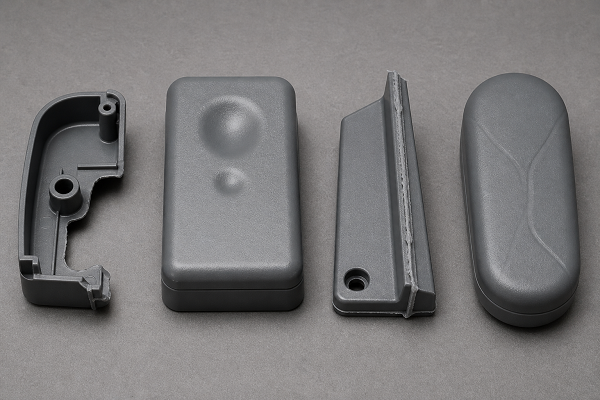
Defects Are Diagnosed, Not Guessed
Each defect has specific root causes related to material, mold design, machine parameters or part geometry. Effective troubleshooting requires identifying the actual cause rather than randomly adjusting parameters.
10How Injection-Molded Parts Are Quality Controlled
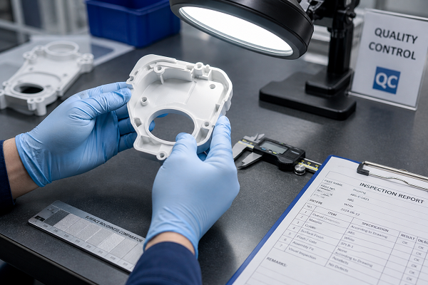
Quality control in injection molding spans the entire production process, from incoming material through final inspection.
Systematic, Not Reactive
Effective QC identifies issues early — at incoming material or first-article stage — rather than relying on end-of-line sorting. Process monitoring during production catches parameter drift before it produces defective parts.
Incoming Material
Verify resin grade against specification. Check material certificates where required. Confirm drying conditions have been met for hygroscopic materials. Validate lot consistency.
First Article / T1 Inspection
Inspect the first parts from a new mold or production run: critical dimensions, appearance, fit with mating parts and functional features. First-article approval gates the start of production.
Process Monitoring
Monitor melt temperature, injection pressure, holding pressure, cooling time and cycle parameters. Statistical process control (SPC) tracks parameter trends and flags drift before out-of-spec parts are produced.
In-Process Inspection
Periodic checks during production: visual appearance, critical dimensions and functional tests. Inspection frequency depends on part criticality and production stability.
Final Inspection & Packaging
Final dimensional verification, appearance grading, quantity confirmation and protective packaging. Inspection reports and material certifications are prepared for shipment.
11What Determines Injection Molding Cost?
Injection molding cost depends on multiple interacting factors. No single number applies across projects.
Tooling
Mold design, material and complexity — typically the largest upfront cost
Resin
Material grade, market price and part weight per shot
Cycle Time
Shorter cycles lower per-part cost — driven by part design and cooling
Cavity Count
Multi-cavity molds produce more parts per cycle but cost more to build
Finishing
Secondary operations: trimming, painting, assembly, decoration
Order Quantity
Higher volumes spread tooling cost over more parts, reducing unit cost
Mold design, materials, lead time and tooling cost factors explained.
In-depth technical analysis of the injection molding process and industry data.
12From Prototype to Production
Most injection molding projects follow a progression from concept to validated production. Understanding this path helps plan timelines and budgets.
(3D print / CNC)
Decision
& Build
Validation
DFM review, mold design, tooling, T1 sampling and optimization.
?Frequently Asked Questions
Related Injection Molding Resources
Mold design, tooling, T1 sampling and process optimization.