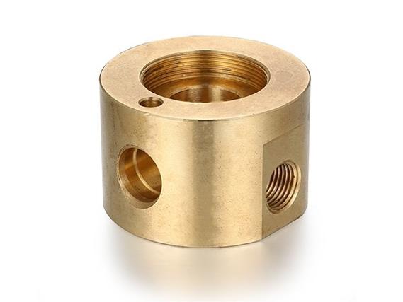
Copper materials are widely used in precision part manufacturing due to their excellent electrical conductivity, thermal conductivity, and corrosion resistance. Below, I will outline the key aspects of CNC machining precision copper parts, covering material selection, machining techniques, process optimization, post-processing, and design considerations.
The following table provides a quick overview of copper material characteristics and selection points to guide your choice.
| Property/Type | Brass | Bronze | Red Copper (Pure Copper) |
|---|---|---|---|
| Common Grades | H62, H65, H70 | – | – |
| Main Characteristics | Most commonly used, good machinability, cost-effective | Good wear resistance, often used in bearings, worms | Excellent electrical/thermal conductivity, but soft material |
| Machining Challenges | High thermal expansion, tendency for tool adhesion | Relatively poor machinability | Soft, prone to deformation during machining |
| Application Scenarios | Medical devices, electronics, consumer goods | Components under high friction/wear | Parts requiring high conductivity |
- Material Selection and Key Machining Techniques
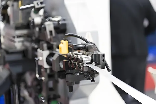
Precision copper part machining focuses on controlling deformation and tool adhesion. Use symmetrical layered milling to distribute stress evenly and opt for vacuum chucks or flexible fixtures to minimize clamping distortion. For tool adhesion, diamond-coated tools with oil-based coolants or minimum quantity lubrication reduce friction and improve surface finish. To achieve high surface quality, ensure cutting tools are sharp and well-maintained; for grinding steps, dress wheels finely and use semi-dull abrasives for micro-level polishing with low feed rates and multiple passes. - Optimized Machining Process Flow
A structured process ensures accuracy. Start with CAM programming and simulation to avoid collisions. For complex parts, 5-axis CNC centers allow single-setup machining, achieving tolerances up to ±0.005mm. The workflow includes:- Roughing: Remove bulk material with higher feeds, leaving 0.1–0.3mm allowance.
- Semi-finishing: Improve dimensional accuracy uniformly.
- Finishing: Use low speeds, sharp tools, and ample coolant for final tolerances.
Always clear corners and dead zones before finishing to prevent tool breakage, and add semi-finishing for uneven residues.
- Post-Machining Treatments and Inspection
Post-processing enhances durability and appearance. Deburr manually or via vibratory polishing. Surface treatments like chemical polishing add shine, while electroplating (e.g., nickel/chrome) boosts wear resistance. Passivation creates an anti-oxidation layer. Finally, verify dimensions with CMM or CT scanning for micron-level checks.
- Design for Manufacturing Tips
Design choices impact manufacturability. Avoid sharp internal corners—add fillets for CNC tools. Maintain minimum wall thickness (≥0.8mm for metals) to prevent deformation. Limit depth-to-width ratios in cavities to ease machining, and design for minimal setups to reduce error accumulation.