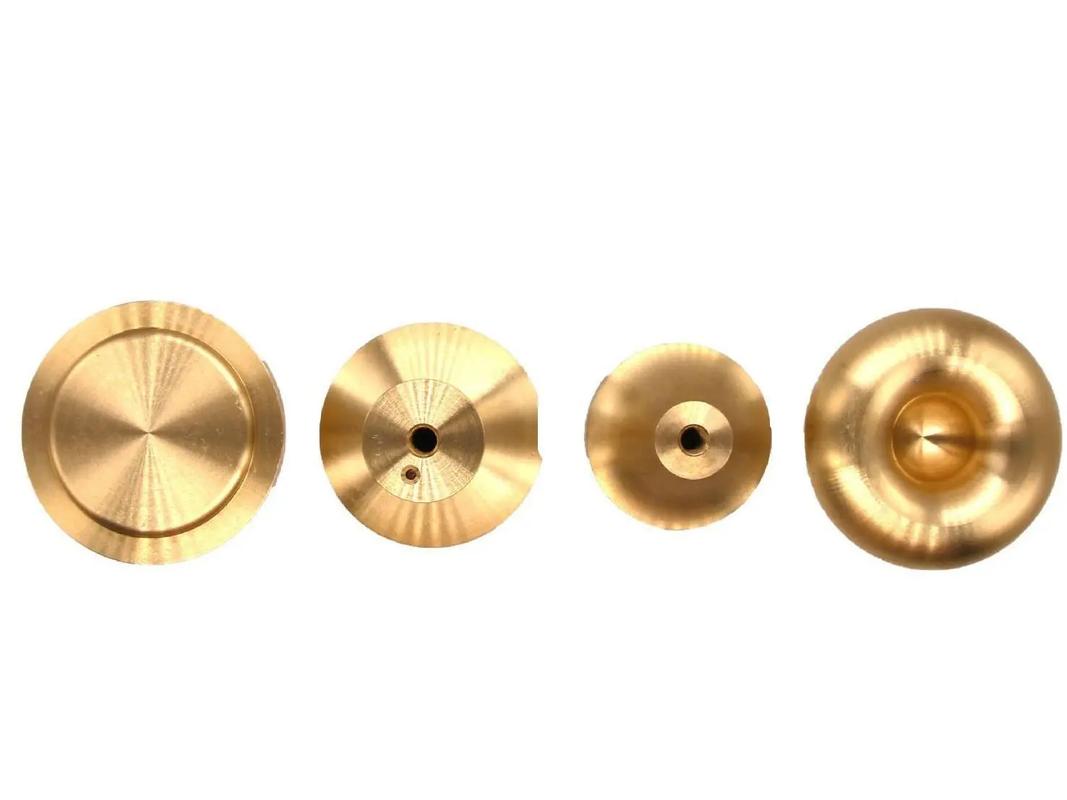
The process flow of CNC machining of precision copper parts can be roughly divided into the following steps:
- Design and Programming: First, according to the product drawings or design requirements, a 3D model is drawn using CAD (Computer – Aided Design) software and converted into a format recognizable by CAM (Computer – Aided Manufacturing) software. In the CAM software, engineers set tool paths, cutting parameters, etc., according to the machining requirements, and generate G – codes or M – codes, which are the “language” of CNC machines.
- Material Preparation: Select copper materials that meet the requirements and carry out necessary pre – treatments, such as cutting into billets of appropriate size and removing the oxide skin.
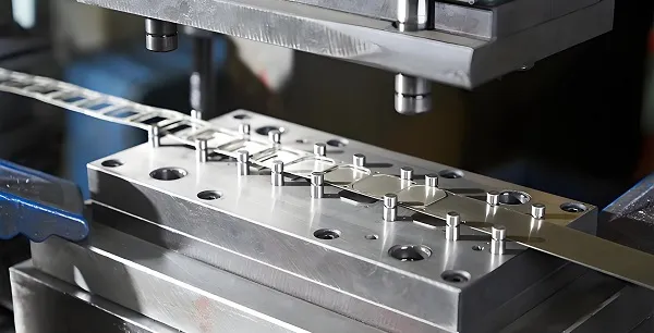
- Clamping and Positioning: Fix the copper billet on the CNC machine tool, and ensure its stability and accuracy during the machining process through fixtures and positioning devices.
- Machining Process: Start the CNC machine tool and carry out machining according to the preset program. During the machining process, the numerical control system automatically adjusts the movement of each axis of the machine tool to complete operations such as cutting, drilling, and milling.
- Inspection and Correction: After machining, use measuring tools to inspect the finished product to ensure that the dimensional accuracy and surface quality meet the requirements. If necessary, fine – tune the machining program according to the inspection results to optimize the machining effect.
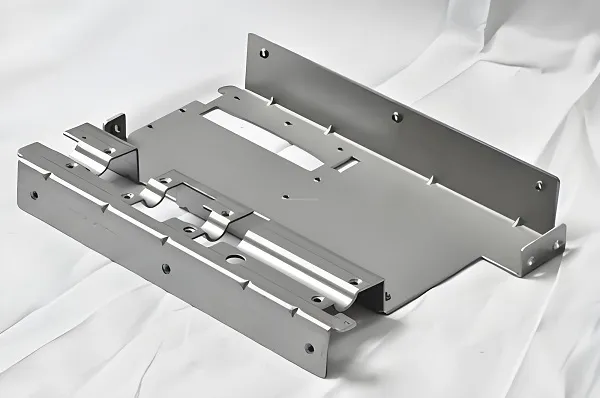
- Post – processing: Perform subsequent operations such as cleaning, deburring, and rust – proof treatment on the machined copper parts, and prepare them for delivery or further processing.
- Characteristics of Copper Materials
There are a wide variety of copper alloys. In this lesson, free – machining brass is taken as an example.
- Common Brass: It has extremely good plasticity and relatively high strength. It has good machining performance, is easy to weld, and is very stable against general corrosion, but is prone to cracking.
- Aluminum Brass: It has high strength. Its corrosion resistance is the best among all brasses. The tendency of stress – corrosion cracking is not significant. Its plasticity is low at room temperature, and its hot – working performance is good.
- Iron Brass: It has high strength and hardness, good machinability, but its plasticity decreases. It can only be hot – worked. Its corrosion resistance is fair, and there is a tendency of stress – corrosion cracking.
- Red Copper: It is a relatively pure type of copper, which can generally be approximated as pure copper. It has good electrical conductivity and plasticity, but its strength and hardness are relatively poor.
- Tool Selection
Selecting the right tool can achieve smooth chip flow and a good copper surface finish.
It is recommended to use a two – flute carbide end – mill with a helix angle greater than 45° for milling copper.
The two – flute geometry provides good chip clearance, facilitates chip evacuation, and reduces the chance of copper friction – welding to the tool. In addition, a two – flute end – mill provides better strength than a single – flute end – mill, so it can withstand greater cutting forces.
A higher helix is preferred because it provides smooth chip movement away from the tool, avoiding chip accumulation around the cutting edge. It also helps to increase the feed rate and improve the surface finish of the cut by providing better shearing action on the chip.
- Tool Life
Milling copper requires sharp tools, but the toughness of copper and the formation of built – up edges will greatly shorten the tool life.
Increasing the RPM and reducing the depth of cut can extend the tool life by minimizing the formation of built – up edges. Using adaptive tool – path technology can also extend the tool life by maintaining a constant chip load.
In addition, a good lubrication system will reduce friction, dissipate excess heat, and extend the tool life.
- Lubrication
When dealing with brittle metals, most of the heat is dissipated by discontinuous chips, protecting the tool and workpiece from overheating.
However, in the case of continuous chip formation, proper heat dissipation does not occur, and the chips may harden during machining. These work – hardened chips can be much harder than the base metal and can easily weld to the workpiece or cutting tool. Re – milling the work – hardened chips welded to the workpiece will dull the tool and accelerate tool wear.
This problem can be avoided by using a good lubricant that will promote chip clearance and carry away the heat from the cutting tool. Another reason for using a good lubricant is poor surface finish and large burrs on the workpiece. Sufficient lubricant (mist or flood) is a good way to solve this problem. Spraying WD – 40 in the milling area and some intermittent sprays during the milling process will improve the surface finish of copper.
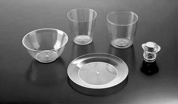
- Workpiece Requirements: The blank material is a 14 – mm – wide hexagonal bar.
- Part Analysis:
- According to the structural characteristics of the drawing, it needs to be clamped with the head turned. Make a fixture open – loop threaded sleeve, the same as in section 2.4.4.
- The graphic features include four parts: threads, grooves, straight lines, and arcs. According to the graphic requirements, select 3 tools: T0101 external turning tool (YG8), T0202 grooving tool (2 – mm wide), and T0303 threading tool.
- Machining Process:
- Make the open – ended threaded sleeve as in section 2.4.4.
- Clamp the blank, leaving a length of 19.5 mm. Use a parting tool to face the end by 0.5 mm and machine the groove.
- Change to the threading tool to machine the thread.
- Clamp with the head turned, screw the machined thread into the fixture open – loop threaded sleeve. Clamp the threaded sleeve with a three – jaw chuck. Machine the inclined – plane dimensions.
- Clamp with the head turned again to machine the large – arc part.
What is an adaptive tool path?
An adaptive tool path is a technology that maintains a constant chip load on the tool throughout the cutting process. It changes the tool path with a slight fillet at the start and end of the cut to facilitate easy entry and exit of the tool from the workpiece.
What are the alternatives to copper milling?
The best alternatives to milling copper are using a fiber laser cutter and engraver. The wavelength of the fiber laser is 1060 nm, which is easily absorbed by copper. This enables precise and complex cutting of copper using a fiber laser. In addition, since laser cutting and engraving are non – contact processes, there is no problem of copper sticking to the cutting tool.
Can we perform drilling operations on pure copper?
Yes, drilling operations can be performed on pure copper.
The drilling operation on pure copper faces similar problems to milling, but due to the smaller space for chip flow during the drilling process, the chips are more likely to be locked into the drill bit. This makes the process more challenging than milling pure copper.