CNC complex machining parts refer to components with intricate geometries, multi-process integrations, or ultra-tight tolerances (often ±0.005 mm or smaller), relying on CNC machining for production. They underpin critical sectors like aerospace (turbine blades), medical devices (implant components), and automotive (high-precision transmission parts). Below, we address key technical questions about manufacturing these parts.
Q1: What Defines “CNC Complex Machining Parts”?
CNC complex parts are distinguished by:
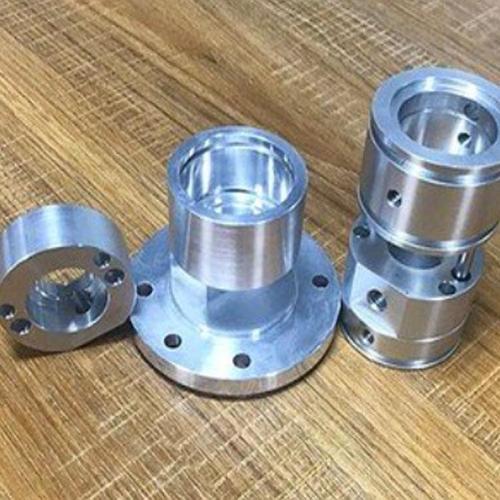
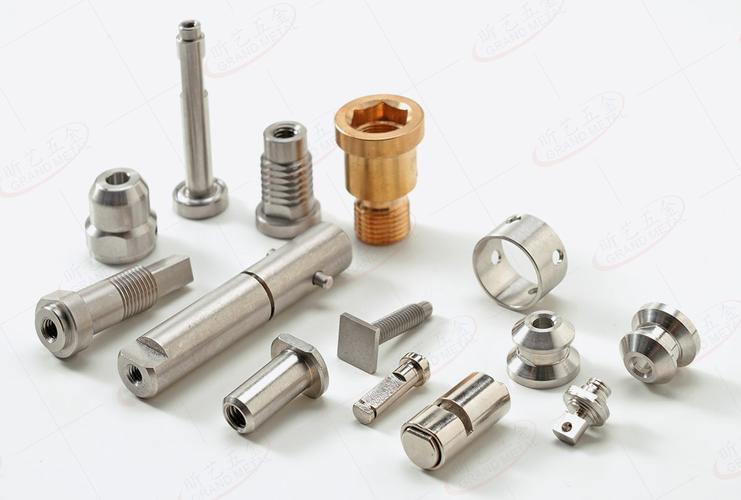
- Intricate Geometry: Free-form surfaces (e.g., aerospace turbine blades with 3D curved profiles), non-circular contours (hexagonal shafts, splined features), or micro-scale structures (≤0.1 mm grooves in medical instruments).
- Multi-Process Integration: Combining turning, milling, drilling, and threading in a single setup (e.g., a hydraulic valve with internal bores, external threads, and radial holes).
- Stringent Tolerances: Dimensional tolerances of ±0.005 mm, and geometric tolerances such as concentricity ≤0.003 mm or flatness ≤0.01 mm over 100 mm.
Example: An aerospace turbine blade requires a 3D airfoil profile with ±0.01 mm contour accuracy and a surface finish of Ra ≤0.4 μm.
Q2: What Special Hardware Is Required for CNC Complex Machining?
Complex machining demands specialized hardware across systems:
1. Spindle System
- Speed & Torque: Ranges from 10,000–40,000 rpm (for high-speed milling of aluminum alloys) to 50–5,000 rpm (for high-torque roughing of titanium, with torque ≥100 N·m).
- Runout Control: Radial runout must be ≤0.001 mm to prevent misalignment of features.
2. Feed System
- Guideways: Roller linear guideways (precision class H1) with positioning accuracy of ±0.001 mm.
- Drives: Direct-drive motors (for 5-axis synchronization) or high-precision C3-grade ball screws (lead error ≤0.003 mm per 300 mm).
3. Tooling
- Multi-Functional Tools: Indexable inserts with complex geometries (e.g., ball-end mills for 3D surfaces, thread mills for variable-pitch threads).
- Tool Holders: Hydraulic chucks (runout ≤0.002 mm) or shrink-fit holders (for high-speed stability).
4. Fixtures
- Modular Fixtures: Quick-change systems (e.g., zero-point positioning) to switch workpieces in ≤1 minute, with repeat accuracy of ±0.002 mm.
- Custom Jigs: For irregular parts (e.g., aerospace brackets), 3D-printed jigs that match the part’s unique shape.
Q3: What Core Algorithms Enable Complex Contour Machining?
Complex shapes rely on advanced CNC control algorithms:
1. NURBS Interpolation
Non-Uniform Rational B-Splines (NURBS) enable precise fitting of free-form surfaces. For a turbine blade’s airfoil:
- Interpolation error is kept ≤0.001 mm.
- Calculation frequency is ≥1,000 Hz (to ensure smooth tool motion).
2. Multi-Axis Synchronization
For 5-axis machining (simultaneous movement of X, Y, Z, A, and B axes):
- Kinematic Modeling: Compensates for axis coupling (e.g., A-axis rotation impacting X/Z positions).
- Look-Ahead Control: Preprocesses 100+ tool paths to optimize acceleration (≤5,000 mm/s²) and avoid vibration.
3. Adaptive Feed Rate
Based on real-time cutting force (measured via spindle-mounted sensors):
- If force exceeds 5 kN (during titanium roughing), the feed rate is reduced by 15%.
- In low-force regions (e.g., aluminum finishing), the feed rate is increased to 2,000 mm/min.
Q4: How to Ensure Machining Precision for Complex Parts?
Precision is achieved through detection, compensation, and calibration:
1. In-Process Measurement
- Touch Probes: Devices like the Renishaw MP250 (accuracy ±1 μm) measure features mid-machining (e.g., bore diameter after roughing).
- Laser Scanners: Capture 3D contours (e.g., a turbine blade’s profile) with a resolution of ≤0.002 mm.
2. Error Compensation
- Thermal Compensation: Sensors monitor spindle/feed axis temperature (resolution 0.1°C), adjusting positions to offset thermal growth (e.g., Z-axis compensation of ±0.001 mm/°C).
- Geometric Compensation: Input 21+ error parameters (e.g., straightness, perpendicularity) into the CNC to correct machine inaccuracies.
3. Post-Process Calibration
- CMM Inspection: Coordinate Measuring Machines (accuracy ±0.001 mm) verify critical dimensions (e.g., hole position in a medical implant).
- Spindle Calibration: Dynamic balance correction (to G0.4 grade) reduces vibration-induced errors.
Q5: What Challenges Arise When Machining Difficult Materials (Titanium, Inconel)?
Hard materials like Ti-6Al-4V or Inconel 718 pose three key challenges:
1. High Cutting Forces
- Solution: Use carbide inserts with AlCrN coating (to reduce friction) and optimize parameters: cutting speed V = 60–120 m/min, feed rate f = 0.05–0.1 mm/r, depth of cut aₚ = 0.5–1 mm.
2. Severe Tool Wear
- Tool Life: Only 15–30 minutes for roughing Ti-6Al-4V.
- Mitigation: Apply high-pressure coolant (20–30 MPa) to flush chips and cool the cutting edge.
3. Thermal Deformation
- Material Trait: Low thermal conductivity (Ti-6Al-4V has 7.6 W/m·K, 1/5 of steel) causes heat buildup.
- Strategy: Use intermittent cutting (with air blast between passes) to keep part temperature <150°C.
Q6: What Are Tips for CNC Programming of Complex Parts?
Effective programming streamlines complex part production:
1. Process Planning
- Step-by-Step Machining: Sequence operations as roughing → semi-finishing → finishing, and optimize tool changes (e.g., use the same tool for multiple features to reduce change time).
- Fixture Avoidance: Program tool paths to avoid collisions with custom jigs (simulate via CAM software).
2. CAM Simulation
- Virtual Machining: Simulate the entire process (e.g., in NX CAM) to detect overcuts (error ≤0.005 mm) or tool collisions.
3. Post-Processing
- Custom Postprocessors: Tailor G-code for specific CNC machines (e.g., Haas vs. DMG Mori) to ensure axis synchronization.
Q7: What Are the Future Trends in CNC Complex Machining?
The field is evolving toward:
1. Intelligent Machining
- AI-Powered Control: Machine learning predicts tool wear (accuracy ≥90%) and automatically adjusts parameters.
- Digital Twins: Virtual replicas of machines simulate machining outcomes before physical production.
2. Hybrid Manufacturing
- Additive + Subtractive: 3D print near-net shapes, then machine to final precision (reduces material waste by 50% for aerospace parts).
3. Ultra-Precision Technologies
- Nanoscale Machining: Achieve 10 nm-level accuracy for optical or semiconductor components.
By addressing hardware, software, and material challenges, CNC complex machining enables the production of high-value parts across industries. As technology advances, these parts will become even more precise and accessible.