II. Tool Crash Types and Schematic Diagrams (Key Crash Points Marked)
1. Tool-Workpiece Crash (Most Frequent)
Scenario: Excessive depth of cut during roughing or incorrect tool path for curved surface machining, causing the tool shank to hit the protruding part of the workpiece.
Schematic Diagram:
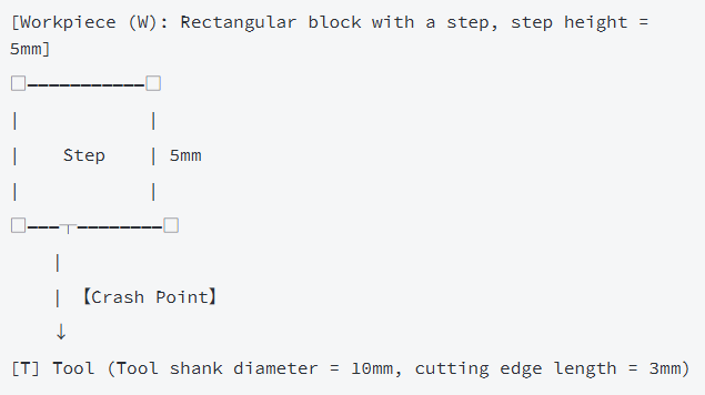
Core Feature: The non-cutting part of the tool shank contacts the non-machined surface of the workpiece, often accompanied by a sudden increase in cutting resistance.
2. Tool-Fixture Crash
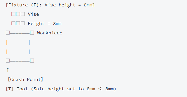
Scenario: The set safe height is lower than the fixture height, causing the tool to hit the vise, locating pin, etc., when lifting.
Schematic Diagram:
3. Tool Change Crash
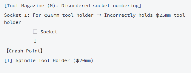
Scenario: Tool magazine disorder or mismatched tool holder specifications, causing the spindle tool holder to collide with the tool magazine socket during tool change.
Schematic Diagram:
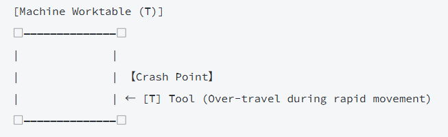
4. Tool-Machine Component Crash
Scenario: Failure to confirm the travel range during rapid movement, causing the tool to hit the worktable, protective cover, etc.
Schematic Diagram:
III. Four-Step Emergency Handling for Tool Crash (1-Minute Golden Response)
Step 1: Emergency Shutdown to Stop Damage
- Immediately press the machine’s red emergency stop button to cut off spindle rotation and axis feed movement. Do not force reset or move the axes;
- Record the on-site status: including the machining stage at the time of the crash (e.g., “2nd segment of roughing”), alarm code (e.g., “ALM 012 Axis Overtravel”), and source of abnormal noise.
Step 2: Damage Severity Assessment
|
Damage Level
|
Judgment Criteria
|
Handling Priority
|
|
Minor Damage
|
Slight tool chipping, local workpiece damage, no machine abnormalities
|
Replace tool → Repair workpiece
|
|
Moderate Damage
|
Tool breakage, workpiece scrapping, no obvious spindle noise
|
Stop machine for inspection → Replace tool
|
|
Severe Damage
|
Spindle noise/vibration, guideway deformation, component displacement
|
Cut off power → Call professional maintenance
|
Step 3: Core Cause Troubleshooting (with Inspection Methods)
Cause 1: Programming Parameter Errors (45% of Cases)
- Typical Issues: Safe height < fixture height (e.g., set to 6mm < 8mm vise height), secondary roughing allowance < primary roughing allowance (e.g., 0.2mm for secondary < 0.3mm for primary);
- Inspection Method: Re-simulate the tool path using Mastercam, focusing on verifying “safe height settings,” “allowance parameters,” and “tool entry/exit methods”;
- Solution: Safe height must be at least 2mm higher than the maximum clamping height; secondary roughing allowance should be 0.05mm larger than the primary one.
Cause 2: Tool Setting and Compensation Errors (30% of Cases)
- Typical Issues: Incorrect tool length compensation value input (e.g., actual length 50mm entered as 48mm), workpiece zero offset;
- Inspection Method: Recheck the tool length with a tool setter, and re-calibrate the workpiece X/Y zero point using an edge finder;
- Solution: Compensation value error must be ≤ 0.002mm; after tool setting, move 10mm in empty to recheck coordinates.
Cause 3: Clamping and Tool Magazine Issues (15% of Cases)
- Typical Issues: Fixture protruding beyond the workpiece edge, mismatch between tool magazine displayed tool number and controller;
- Inspection Method: Visually check the fixture position, and verify that the tool magazine displayed tool number matches the actual tool holder specification;
- Solution: The fixture edge must be ≥ 5mm away from the workpiece machining area; confirm tool number matching before tool change.
Cause 4: Machine and Operation Errors (10% of Cases)
- Typical Issues: Excessive spindle runout (> 0.005mm), accidental touch of the handle during manual operation;
- Inspection Method: Measure spindle runout with a dial indicator, and check operation records to confirm if there was incorrect operation;
- Solution: Professional calibration is required if spindle runout exceeds the limit; use “handwheel mode” for fine adjustment during manual operation.
Step 4: Machining Recovery Verification
- Minor Damage: Replace the tool → Re-set the tool → Dry-run the tool path (raise Z-axis by 20mm) → Test cut in the scrap area;
- Moderate Damage: Inspect spindle precision → Re-program → Monitor the entire process of the first workpiece machining;
- Severe Damage: Do not start the machine; contact the machine manufacturer for maintenance and then perform precision calibration.
IV. Core Prevention Measures for Tool Crash (Key to Zero Accidents)
1. Programming Phase (Source Control)
- Mandatorily implement “triple inspection”: Tool path simulation → Interference detection → Parameter review; safe height must be higher than the clamping height;
- Avoid trimming tool paths; do not use “contour parallel milling” when machining allowance > tool diameter; use “pocket milling” instead.
2. Pre-Operation Preparation (Mandatory Process)
- Return the machine to the reference point first after starting; check the lubrication system oil level and air pressure (≥ 0.6MPa);
- After clamping, measure the workpiece flatness with a dial indicator (re-level if > 0.01mm); attach warning strips to the fixture edge.
3. Machining Process Monitoring
- Dry-run the tool path before machining the first workpiece; raise the Z-axis to a safe height (20mm recommended) to confirm no crash risk;
- Stay at the machine during automatic machining; closely observe the distance between the tool and the worktable during rapid feed; press emergency stop immediately if abnormal noise occurs.
4. Special Specifications for Tool Change
- Before tool change, verify that the tool magazine tool number matches the program tool number; clean oil and dirt from the tool holder/tool socket; do not install tool holders with mismatched tapers;
- Monitor the entire tool change process; stop the machine immediately if tool jamming occurs; do not forcefully insert or pull out the tool.
5. Machine Maintenance Cycle
|
Maintenance Item
|
Cycle
|
Precision Requirement
|
|
Spindle Runout Inspection
|
Monthly
|
≤ 0.005mm
|
|
Guideway Cleaning and Lubrication
|
Before Daily Startup
|
No iron chip accumulation, oil level up to standard
|
|
Tool Magazine Positioning Precision Calibration
|
Quarterly
|
Tool socket repeat positioning error ≤ 0.01mm
|
V. Safety Operation Red Lines (Violations Will Cause Accidents)
- Never operate the machine while wearing gloves; always close the safety door during machining; use special tools to remove chips (do not use hands);
- Do not move the axes rapidly during manual operation; must use “handwheel mode” for fine adjustment;
- Do not perform full automatic machining before program verification; must use the handwheel for test cutting to confirm the tool path for the first workpiece;
- Do not release the emergency stop or restart the equipment before resolving machine alarms.
VI. Summary
The core principle for tool crash prevention: “Error prevention in programming as the premise, operation verification as the key, and maintenance calibration as the guarantee”. 80% of tool crashes are caused by programming parameter errors and tool setting mistakes. By implementing the “simulation – dry run – test cut” triple verification process, the tool crash rate can be controlled below 0.1%. Remember: One standard operation can avoid tens of thousands of yuan in machine maintenance costs.
Disclaimer
- All information, opinions, and data contained in this article are for the purpose of information transmission only and do not constitute any advice on investment, transactions, law, medical care, or other matters.
- The content of the article is compiled based on public information or created based on the author’s personal understanding. Although every effort is made to ensure accuracy, it does not guarantee the completeness, accuracy, and timeliness of the information, nor does it bear any responsibility for any losses caused by the use of the content of this article.
- If the article involves third-party opinions, pictures, data, and other content, the copyright belongs to the original author. In case of infringement, please contact us for deletion.
- Readers should make independent decisions based on their actual situation and combined with professional opinions. The user shall bear all consequences arising from the use of the content of this article.