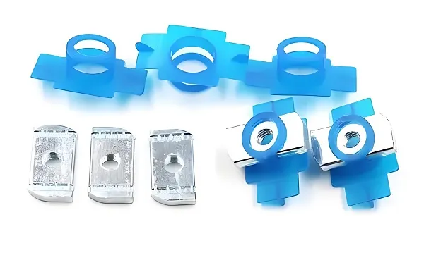
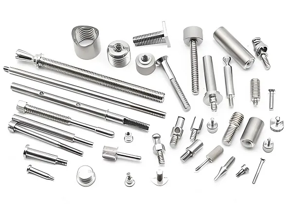
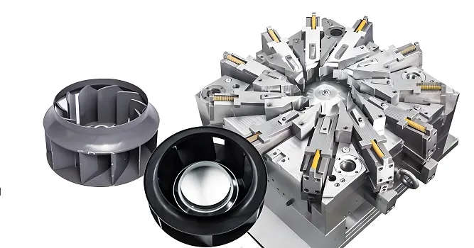
Custom Face milling Parts refer to precision mechanical components manufactured via customized face milling processes, tailored to specific geometric, material, and performance requirements of end-users. Unlike standardized off-the-shelf parts (e.g., mass-produced flat washers), these parts prioritize the machining of flat surfaces (the core feature of face milling) while integrating custom attributes such as non-standard dimensions, special material selections, and ultra-tight flatness tolerances.
The core distinction lies in “process customization” and “performance matching”: face milling (the dominant machining method) is optimized to achieve targeted flat surface quality (e.g., surface roughness Ra ≤ 0.4 μm for sealing applications), while auxiliary processes (e.g., drilling, tapping, surface coating) are added based on functional needs. These parts serve as critical components in equipment where flat surfaces are essential for assembly, sealing, or load-bearing (e.g., automotive engine gaskets, aerospace structural joints).
2. Core Characteristics of Custom Face milling Parts
2.1 Customization-Driven Geometric Flexibility
- Non-standard flat surface dimensions: Thickness ranges from 0.5 mm (micro-electronic parts) to 500 mm (heavy machinery bases), with length/width customizable up to 3000 mm (limited by CNC mill table size).
- Integrated features: Flat surfaces may be combined with custom auxiliary structures, such as:
-
- Locating holes (diameter tolerance ±0.005 mm) for assembly alignment;
-
- Grooves (depth 0.1-5 mm) for coolant flow or seal placement;
-
- Chamfers/fillets (radius 0.1-2 mm) to avoid stress concentration.
2.2 Face Milling-Centric Quality Requirements
- Flatness: The primary quality indicator, with tolerances ranging from ≤0.01 mm/100 mm (aerospace parts) to ≤0.1 mm/100 mm (general industrial parts), controlled via high-precision face milling and post-machining calibration.
- Surface roughness: Determined by application—Ra ≤ 0.2 μm for optical components (to reduce light scattering), Ra ≤ 1.6 μm for mechanical assembly surfaces (to ensure tight fitting), and Ra ≤ 3.2 μm for non-critical structural parts.
- Dimensional stability: Post-machining deformation (due to residual stress) is controlled ≤0.003 mm for high-precision parts, achieved via stress-relief annealing (for metal materials) or low-temperature aging (for plastics).
2.3 Material Diversity for Targeted Performance
Custom Face milling Parts are manufactured from materials selected to match end-use environments, with each material requiring specialized face milling parameters:
|
Material Category
|
Representative Types
|
Key Performance Traits
|
Typical Face Milling Requirements
|
|
Metals
|
Aluminum (6061-T6), Stainless Steel (304), Titanium (Ti-6Al-4V)
|
High strength, corrosion resistance, thermal conductivity
|
Ultra-tight flatness (≤0.005 mm/100 mm), low surface roughness (Ra ≤ 0.8 μm)
|
|
Engineering Plastics
|
PEEK, POM, Nylon 66
|
Lightweight, chemical resistance, low friction
|
Minimal thermal deformation (machining temp ≤ 150°C), no burrs
|
|
Composites
|
Carbon Fiber-Reinforced Polymer (CFRP), Glass Fiber-Reinforced Polymer (GFRP)
|
High strength-to-weight ratio, fatigue resistance
|
Low cutting force (to avoid fiber delamination), dust control
|
3. Core Technical Requirements for Custom Face Milling
3.1 Material-Specific Face Milling Parameter Optimization
The success of custom face milling depends on matching cutting parameters to material properties, as improper parameters lead to poor surface quality or tool damage:
|
Material
|
Tool Type
|
Cutting Speed (V)
|
Feed Rate (fₙ)
|
Depth of Cut (aₚ)
|
Key Notes
|
|
6061-T6 Aluminum
|
4-6 Flute Carbide Face Mill
|
150-300 m/min
|
800-1500 mm/min
|
0.5-2 mm
|
High-speed machining reduces built-up edge (BUE); use emulsion coolant
|
|
304 Stainless Steel
|
8-10 Flute Ultra-Fine Grain Carbide Mill
|
50-100 m/min
|
300-600 mm/min
|
0.3-1 mm
|
Low speed avoids work hardening; high-pressure coolant (3-5 MPa) for chip evacuation
|
|
Ti-6Al-4V Titanium
|
CBN-Coated Carbide Mill
|
30-60 m/min
|
100-300 mm/min
|
0.1-0.5 mm
|
Intermittent cutting reduces heat accumulation; cryogenic cooling optional
|
|
PEEK Plastic
|
High-Speed Steel (HSS) Mill
|
80-120 m/min
|
200-400 mm/min
|
0.2-1 mm
|
Low feed rate prevents melting; air cooling instead of liquid coolant
|
3.2 Precision Control for Flat Surface Quality
3.2.1 Equipment Requirements
- CNC Mill Rigidity: Machine tool frame with vibration damping (natural frequency ≥ 200 Hz) to avoid chatter during face milling—critical for achieving flatness ≤0.005 mm/100 mm.
- Spindle Performance: Dynamic balance grade G0.4 (per ISO 1940-1) at maximum speed, radial runout ≤0.001 mm, and axial runout ≤0.0005 mm to ensure uniform cutting force.
- Linear Guideways: Roller-type guideways (precision class H1) with positioning accuracy ±0.0015 mm and repeatability ±0.0005 mm to maintain consistent feed paths.
3.2.2 Detection and Calibration
- In-Process Monitoring: Use laser displacement sensors (resolution 0.1 μm) to measure flatness in real time during face milling—adjust cutting parameters if deviation exceeds 50% of tolerance.
- Post-Machining Inspection:
-
- Flatness: Test with a precision optical flat (accuracy ±0.0005 mm) or a coordinate measuring machine (CMM, flatness measurement accuracy ≤0.001 mm/100 mm).
-
- Surface Roughness: Measure with a contact-type roughness tester (Ra resolution 0.001 μm) at 3-5 sampling points across the flat surface.
3.3 Custom Fixturing for Part Stability
Custom fixtures are designed to match the unique geometry of the part, ensuring minimal deformation during face milling:
- Clamping Force Optimization: For thin-walled parts (thickness ≤1 mm), use pneumatic clamps with flexible jaws (polyurethane-coated) to apply uniform force (50-100 N), avoiding warpage.
- Locating Datum Alignment: Fixtures integrate precision locating pins (tolerance ±0.002 mm) to align the part with the mill’s X/Y axis—ensuring flat surface parallelism to the datum ≤0.003 mm.
- Modular Fixtures: For low-volume custom parts, use modular tooling (e.g., zero-point positioning systems) to reduce fixture design time by 40% and ensure repeatability ±0.002 mm.
4. Classification of Custom Face milling Parts
Classification is primarily based on application industry and functional requirements, as these determine material selection, precision levels, and auxiliary features:
4.1 Automotive Industry
- Typical Parts: Engine cylinder head mating surfaces, transmission housing flange plates, brake caliper mounting flats.
- Technical Requirements: Flatness ≤0.01 mm/100 mm (to ensure sealing against oil/gas leakage), surface roughness Ra ≤1.6 μm, and material compatibility with engine oils (e.g., 316 stainless steel or 6061-T6 aluminum).
4.2 Aerospace Industry
- Typical Parts: Aircraft wing structural joints, turbine engine compressor stator flats, satellite antenna mounting plates.
- Technical Requirements: Ultra-tight flatness ≤0.005 mm/100 mm (for load distribution), material strength (Ti-6Al-4V or CFRP), and resistance to extreme temperatures (-50°C to 200°C).
4.3 Medical Device Industry
- Typical Parts: Surgical instrument bases (e.g., scalpel handles), diagnostic equipment chassis, implant component mating surfaces (e.g., hip joint spacers).
- Technical Requirements: Biocompatible materials (316L stainless steel or titanium), surface roughness Ra ≤0.4 μm (to prevent bacterial adhesion), and flatness ≤0.008 mm/100 mm (for precise assembly).
4.4 Electronic Industry
- Typical Parts: Printed Circuit Board (PCB) heat sinks, semiconductor equipment vacuum chamber flats, smartphone chassis mounting surfaces.
- Technical Requirements: Lightweight materials (6063 aluminum or magnesium alloy), flatness ≤0.01 mm/100 mm (for heat transfer efficiency), and surface coating compatibility (e.g., anodization for corrosion resistance).
5. Manufacturing Process of Custom Face milling Parts
The process follows a “demand-driven” workflow, integrating customization at each stage:
5.1 Requirements Analysis & Design
- Needs Capture: Collaborate with the user to define key parameters: flat surface dimensions (length/width/thickness), flatness tolerance, surface roughness, material type, and functional features (e.g., holes, grooves).
- 3D Modeling: Use CAD software (SolidWorks, UG NX) to design the part, with special attention to:
-
- Flat surface continuity (no abrupt thickness changes to avoid machining vibration);
-
- Auxiliary feature placement (e.g., holes positioned ≥5 mm from edge to prevent material weakening).
- Process Simulation: Use CAM software (Mastercam, Siemens NX CAM) to simulate face milling paths, verify cutting parameter feasibility, and detect potential collisions (tool vs. fixture).
5.2 Material Preparation
- Material Selection: Source raw materials meeting industry standards (e.g., ASTM B209 for aluminum, ASTM A240 for stainless steel) with certified mechanical properties (hardness, tensile strength).
- Blank Cutting: Cut the raw material into a “blank” with 2-5 mm machining allowance (compensating for material removal during face milling) using sawing or laser cutting.
5.3 Fixture Installation & Part Clamping
- Fixture Setup: Mount the custom fixture on the CNC mill table, calibrate its levelness (≤0.001 mm/m) and alignment with the mill’s axes (parallelism ≤0.001 mm/m).
- Part Clamping: Secure the blank in the fixture, use a dial indicator (accuracy ±0.001 mm) to check part alignment, and adjust clamping force to avoid deformation.
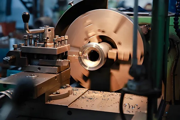
5.4 Face Milling Execution
- Rough Milling: Remove 80-90% of the machining allowance with high material removal rate parameters (e.g., 6061 aluminum: V=250 m/min, fₙ=1200 mm/min, aₚ=1.5 mm) to reduce cycle time.
- Semi-Finish Milling: Reduce allowance to 0.1-0.2 mm with optimized parameters (e.g., V=280 m/min, fₙ=800 mm/min, aₚ=0.3 mm) to improve surface flatness.
- Finish Milling: Achieve final quality with tight parameters (e.g., V=300 m/min, fₙ=500 mm/min, aₚ=0.1 mm) and climb milling (to reduce tool wear and surface scratches).
5.5 Post-Machining Treatment
- Deburring: Remove burrs (height ≤0.005 mm) from flat surface edges using CNC deburring tools or ultrasonic cleaning (for plastic parts).
- Surface Treatment: Apply custom coatings based on requirements:
-
- Anodization (aluminum parts, thickness 5-10 μm) for corrosion resistance;
-
- Passivation (stainless steel parts, 20% nitric acid solution) to enhance rust resistance;
-
- Polishing (medical parts, Ra ≤0.2 μm) for biocompatibility.
- Stress Relief: For metal parts, perform annealing (aluminum: 350°C for 1 hour; steel: 600°C for 2 hours) to eliminate residual machining stress and improve dimensional stability.
5.6 Quality Inspection & Delivery
- Comprehensive Testing: Inspect all custom requirements: flatness (via CMM), surface roughness (via roughness tester), dimensional accuracy (via calipers/micrometers), and material compliance (via spectroscopy).
- Documentation: Provide a “certificate of conformance” including test data, material certification, and process records (for industries with strict traceability requirements, e.g., aerospace, medical).
6. Quality Control and Common Challenges
6.1 Key Quality Control Measures
- Process Stability Monitoring: Track cutting force (via spindle-mounted sensors, resolution 0.1 N) and spindle vibration (via accelerometers, resolution 0.01 mm/s)—halt machining if force exceeds 5 kN (for steel) or vibration exceeds 0.1 mm/s.
- Statistical Process Control (SPC): Collect data from 30+ consecutive parts to calculate process capability (Cₚ ≥ 1.33 for critical dimensions) and identify deviations early.
- Environmental Control: Maintain workshop temperature (20±2°C) and humidity (40-60%) to avoid thermal deformation of parts and equipment—critical for achieving flatness ≤0.005 mm/100 mm.
6.2 Common Challenges and Solutions
|
Challenge
|
Root Cause
|
Solution
|
|
Flatness Deviation (>0.01 mm/100 mm)
|
Spindle runout (>0.001 mm); fixture levelness error (>0.001 mm/m)
|
Recalibrate spindle bearings; re-level fixture and verify with laser interferometer.
|
|
Surface Scratches (Ra > 1.6 μm)
|
Chip re-cutting; tool wear (flank wear VB >0.3 mm)
|
Increase coolant pressure to 4 MPa; replace tool and reset cutting parameters.
|
|
Part Deformation (Thin-Walled Parts)
|
Clamping force too high (>100 N); cutting heat accumulation (>200°C)
|
Reduce clamping force to 50-80 N; use air cooling (for plastics) or cryogenic cooling (for metals).
|
|
Material Delamination (Composites)
|
Cutting force too high (>2 kN); tool edge dull
|
Use diamond-coated tools with sharp cutting edges; reduce depth of cut to 0.1 mm.
|
7. Development Trends of Custom Face milling Parts
7.1 Intelligent Machining
- AI-Driven Parameter Optimization: Machine learning models (trained on 10,000+ machining cycles) auto-select face milling parameters based on material and part geometry—reducing setup time by 50% and improving flatness consistency by 30%.
- Digital Twins: Virtual replicas of the manufacturing process (integrating part design, machine status, and environmental data) predict machining defects (e.g., chatter-induced flatness errors) before physical production—lowering scrappage rates by 40%.
7.2 Material Innovation
- Advanced Composites: Wider adoption of CFRP and metal matrix composites (MMCs) for lightweight, high-strength parts—requiring specialized face milling tools (e.g., diamond-impregnated cutters) and low-force machining strategies.
- Bio-Based Plastics: Use of PLA (polylactic acid) and PHA (polyhydroxyalkanoates) for eco-friendly parts—demanding low-temperature machining (≤120°C) to avoid material degradation.
7.3 Green Manufacturing
- Minimum Quantity Lubrication (MQL): Replace traditional coolant with 5-10 mL/h of vegetable oil-based lubricant—reducing coolant waste by 99% and eliminating environmental pollution from coolant disposal.
- Energy-Efficient Equipment: Use high-efficiency CNC mills (energy consumption reduced by 25% vs. traditional models) and regenerative spindle drives (recover 15% of energy during deceleration) to lower carbon footprint.
8. Conclusion
Custom Face milling Parts serve as critical components in industries requiring precision flat surfaces and tailored performance. Their technical value lies in the integration of “customization flexibility” and “face milling precision”—from material selection to process optimization, every stage is designed to meet unique user needs. As manufacturing technology advances, trends such as intelligent parameter optimization, composite material application, and green machining will further expand the capabilities of custom face milling, enabling higher precision (flatness ≤0.003 mm/100 mm) and broader industry adoption (e.g., quantum computing equipment, space exploration components).
For users seeking custom face milling solutions, collaboration with manufacturers specializing in material-specific machining is essential—ensuring that parts not only meet geometric requirements but also perform reliably in their intended application environments.