Answer
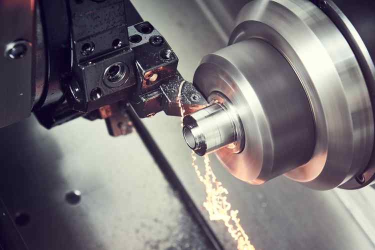
CNC milling (Computer Numerical Control Milling) is a manufacturing process where a numerically controlled system guides a rotating tool to move along multiple axes, cutting workpiece materials. The working principle is: first, design a 3D part model with CAD software, then generate machining paths (G-code) via CAM software and input them into the CNC milling machine’s control system. The machine’s servo motors drive the worktable or tool to move along the X, Y, Z axes (or more) based on instructions. A high-speed rotating milling cutter removes materials through operations like face milling, contouring, or cavity machining, forming parts that meet design requirements. Suitable for various materials such as aluminum alloys, steel, and plastics, this process enables automated production of high-precision, complex-shaped parts.
Extended Answer
I. Technical Background and Definition of CNC Milling
CNC milling emerges from the integration of traditional milling and numerical control technology. While traditional milling relies on manual operation with limited precision and efficiency, CNC milling achieves automated, high-precision machining through computer program-controlled tool movements. Its core is the “numerical control system,” which uses digital instructions (e.g., G-code, M-code) to control the displacement of machine axes and tool actions, making the milling cutter remove materials along preset trajectories. Classified by machine structure, it includes vertical milling, horizontal milling, and 5-axis milling, with the latter widely used in aerospace for its multi-angle machining capability.
II. Working Principle: Hardware-Software Collaboration in CNC Milling
(1) Hardware Components
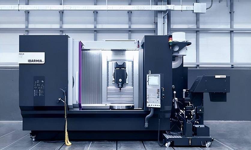
- CNC Milling Machine Body: Comprises the bed, worktable, spindle box, etc., providing mechanical structure for machining. The worktable fixes the workpiece, and the spindle drives the tool to rotate at high speed (10,000–40,000 rpm).
- CNC Controller: Brands like FANUC and SIEMENS receive and parse machining instructions, controlling servo motors via drivers to achieve precise axis displacement (accuracy up to ±0.01mm).
- Tool System: Diverse milling cutters include end mills, ball-nose mills, slot drills, and form cutters, selected based on requirements (e.g., planes, curves, grooves). Tool materials like high-speed steel (HSS), cemented carbide (WC), or ceramics balance wear resistance and cutting efficiency.
(2) Software Workflow
- CAD Modeling: Design 3D part models with SolidWorks, UG, CATIA, etc., specifying dimensions, tolerances, and surface roughness.
- CAM Programming: Import CAD models into CAM software (e.g., Mastercam, PowerMill), set machining strategies (roughing, finishing), tool paths, and cutting parameters (speed, feed rate, depth), generating CNC programs (G-code).
- Program Transmission and Execution: Transfer G-code to the machine controller via USB or network. The system parses instructions to drive motor movements, with real-time position feedback forming a closed-loop control (e.g., scale rulers detect and correct displacement errors).
III. Detailed Process of CNC Milling
(1) Preparations
- Workpiece Clamping: Fix the workpiece with vices, chucks, or special fixtures to ensure no displacement and avoid vibration affecting precision.
- Tool Setting: Determine the relative position between the tool and workpiece, set coordinate system origins (G54–G59), often completed with tool setters or trial cutting.
- Cutting Parameters:
- Spindle speed (S): Depends on material hardness and tool diameter, e.g., 2,000–8,000 rpm for aluminum machining.
- Feed rate (F): Tool movement per minute, typically 100–2,000 mm/min, balancing efficiency and surface quality.
- Cutting depth (ap): Larger for roughing (1–5 mm), usually <0.5 mm for finishing.
(2) Machining Execution
- Rough Milling: Rapidly remove most excess material, using layered cutting (Z-axis stratification) to reduce tool load, with tool paths often zigzag or spiral.
- Finish Milling: Machine surfaces to design dimensions, with tool paths following part contours to ensure tolerances (e.g., ±0.05 mm) and surface roughness (Ra 0.8–3.2 μm).
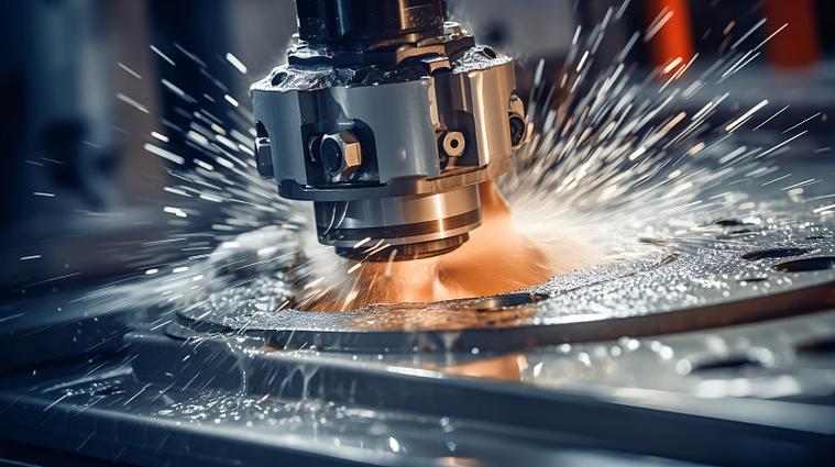
- Cooling and Lubrication: Use cutting fluids (water-soluble or oily) to reduce temperature, minimize tool wear, and flush chips (e.g., emulsion for cast iron, mineral oil for aluminum).
(3) Quality Inspection
- Use coordinate measuring machines (CMM), calipers, or profilometers to check dimensions and geometric tolerances (e.g., flatness, perpendicularity) for blueprint compliance.
IV. Core Machining Types in CNC Milling
(1) Face Milling
- Machine planes with end mills or face mills, commonly for part datum surfaces or cover plates. Requires low tool axial runout (<0.02 mm) to ensure flatness.
(2) Contour Milling
- Follow 2D part contours for machining bosses, grooves, or complex shapes, generating continuous tool paths via CAM software (e.g., G01 linear interpolation, G02/G03 circular interpolation).
(3) Cavity Milling
- Machine enclosed cavities (e.g., mold cavities). Drill entry points first, then remove materials via helical ramping or layered cutting to avoid tool damage from excessive axial force.
(4) 3D Surface Milling
- For complex surfaces like aero-engine blades or automotive molds, use ball-nose mills with 5-axis 联动 (X, Y, Z + rotational A/B/C axes). Achieve surface fitting via “contour” or “radial” paths, with machining accuracy of 0.01–0.1 mm.
V. Application Fields and Typical Cases of CNC Milling
(1) Aerospace
- Machine aluminum fuselage frames and titanium engine parts (e.g., impellers). 5-axis milling enables high-precision machining of thin-walled parts (wall thickness <1 mm) and complex inner cavities, requiring cutting force control to prevent deformation.
(2) Automotive Manufacturing
- Produce engine blocks and transmission casings (cast iron or aluminum). High-speed milling (HSM) improves efficiency, combined with automated production lines for batch processing.
(3) Medical Devices
- Machine titanium orthopedic implants (e.g., joint prostheses). 5-axis milling achieves personalized surface modeling, with surfaces polished to meet biocompatibility requirements.
(4) Mold Manufacturing
- Machine cavities and cores for injection or die-casting molds. Use graphite or tool steel, achieving high-precision surfaces via electrical discharge milling (EDM) or hard milling (processing materials >50HRC).
VI. Advantages and Challenges of CNC Milling
(1) Core Advantages
- High Precision and Consistency: Under CNC control, part tolerances stay within ±0.01 mm, ideal for maintaining quality in batch production.
- Complex Shape Machining: Multi-axis 联动 and CAM programming enable structures like undercuts, deep cavities, and free-form surfaces impossible with traditional processes.
- Automation and Efficiency: Complete multiple operations (milling, drilling, tapping) in one setup, reducing manual intervention and shortening cycle times.
- Wide Material Adaptability: Machine metals (steel, aluminum, titanium), plastics, composites, etc., by adjusting tools and parameters.
(2) Faced Challenges
- Equipment and Programming Costs: 5-axis CNC mills are expensive (hundreds of thousands to millions of yuan), and CAM programming requires professionals, raising barriers for SMEs.
- Cutting Efficiency and Tool Wear: Machining hard materials (e.g., quenched steel) wears tools quickly, requiring frequent replacement and affecting productivity.
- Process Optimization Difficulty: Tool path planning for complex parts must balance efficiency and precision (e.g., avoiding tool resonance in high-speed milling), relying on engineer experience.
VII. Technological Development Trends of CNC Milling
- Integration of High Speed and High Precision: Electro-spindle technology (>40,000 rpm) and linear motor drives enable “high-speed cutting + micron-level precision” (e.g., mirror milling for molds).
- Intelligence and Digitalization: Introduce AI algorithms to optimize cutting parameters, simulate machining via digital twin technology, and predict tool life/deformation risks.
- Multi-Process Integration: Compound machines (e.g., milling-turning, milling-grinding) complete multi-process machining in one setup, reducing clamping errors.
- Green Machining: Promote dry cutting (no coolant) or minimum quantity lubrication (MQL) to reduce environmental pollution and costs.
VIII. Comparison with Other Machining Processes
| Process Type | CNC Milling | CNC Turning | 3D Printing | Stamping |
|---|---|---|---|---|
| Machining Principle | Tool rotation + multi-axis cutting | Workpiece rotation + linear tool cutting | Layered material deposition | Mold stamping forming |
| Suitable Shapes | Complex surfaces, polyhedrons | Rotational bodies (cylinders, cones) | Hollow structures, customized parts | Batch flat parts, simple shapes |
| Precision | ±0.01–0.1 mm | ±0.01–0.05 mm | ±0.1–0.5 mm | ±0.1–0.2 mm |
| Material Utilization | Low (material removal) | Medium | High (minimal waste) | Medium |
| Batch Adaptability | Small to medium batches (1–1,000 pieces) | Small to medium batches | Single piece/small batches | Large batches (>10,000 pieces) |
Conclusion
CNC milling, through deep integration of numerical control and machining technologies, has become a core process in modern manufacturing. Its full workflow from “digital design-automated machining-intelligent inspection” supports the precision and efficiency needs of high-end equipment manufacturing. With the development of intelligent manufacturing, CNC milling will play a more critical role in complex part machining, green production, and flexible manufacturing.