CNC machining transforms raw materials into precision parts using computer-controlled tools, offering accuracy (±0.005mm), repeatability, and versatility across industries from aerospace to automotive. Whether producing a single prototype or 100,000+ units, the process demands careful planning, material selection, and technical expertise. Goldcattle, with 26 years in CNC manufacturing, outlines the step-by-step workflow to create high-quality CNC parts—from design to final inspection—backed by ISO 9001 and AS9100D certifications.
Step 1: Define Part Requirements & Material Selection
The foundation of successful CNC machining lies in clarifying part specifications and choosing the right material to balance performance, cost, and machinability.
Key Considerations:
- Functional requirements: Tolerances (±0.005mm for aerospace vs. ±0.1mm for structural parts), surface finish (Ra 0.02μm for bearings vs. Ra 1.6μm for brackets), and mechanical properties (tensile strength, corrosion resistance). A medical instrument part might require 316L stainless steel (515MPa tensile strength) for biocompatibility, while a lightweight bracket could use 6061 aluminum (310MPa).
- Material machinability: Select materials based on ease of cutting, tool wear, and finish:
|
Material
|
Machinability Rating*
|
Key Properties
|
Ideal Applications
|
|
Aluminum (6061-T6)
|
100%
|
Lightweight, 310MPa tensile strength
|
Automotive parts, electronics enclosures
|
|
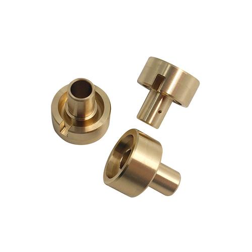
Brass (C36000)
|
85%
|
Excellent chip control, 345MPa tensile strength
|
Plumbing fittings, electrical components
|
|
Stainless Steel (304)
|
45%
|
Corrosion-resistant, 515MPa tensile strength
|
Medical devices, food processing equipment
|
|
Titanium (Ti-6Al-4V)
|
20%
|
High strength-to-weight ratio, 895MPa tensile strength
|
Aerospace components, high-stress parts
|
*Higher = easier to machine
Step 2: Design & CAD/CAM Engineering
CNC parts require designs optimized for machining—using CAD (Computer-Aided Design) and CAM (Computer-Aided Manufacturing) software to ensure manufacturability and precision.
Critical Design Elements:
- Tolerance definition: Specify achievable tolerances based on part size and feature complexity (e.g., ±0.002mm for holes <10mm diameter, ±0.01mm for lengths >300mm). Use GD&T (Geometric Dimensioning and Tolerancing) to clarify positional, runout, and flatness requirements.
- Machining-friendly features:
-
- Avoid sharp internal corners (use ≥0.5mm radii) to prevent tool breakage and reduce stress concentration.
-
- Design uniform wall thickness (≥1mm for metals) to minimize vibration and warping during cutting.
-
- Include tool clearance (≥3× tool diameter) for deep cavities or undercuts.
- CAM programming: Convert CAD models (STEP/IGES) into machine-readable code (G-code/M-code) with:
-
- Toolpath optimization (climb milling for better finish, trochoidal milling for reduced tool wear).
-
- Feed rate/speed selection (1000mm/min for aluminum vs. 300mm/min for titanium).
-
- Coolant application points to prevent heat-induced distortion.
Step 3: Choose CNC Machining Process
Select the right CNC technology based on part geometry, material, and production volume—each method offers unique advantages for specific features.
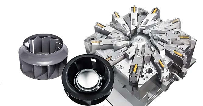
1. CNC Milling (Best for Prismatic Parts)
- Process: Uses rotating cutting tools to remove material from solid blocks, with 3-axis to 5-axis capabilities. 5-axis machines tilt the part or tool to access multiple faces in one setup, ideal for complex 3D contours (e.g., turbine blades).
- Applications: Brackets, housings, and parts with holes, slots, or pockets. A 5-axis milled aerospace bracket with 8 inclined holes achieved ±0.003mm positional accuracy across all features.
- Advantages: Handles complex shapes, 适合多种材料,and achieves tight tolerances (±0.005mm).
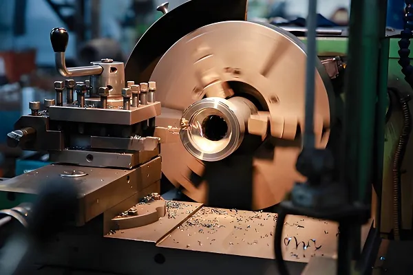
2. CNC Turning (Best for Rotational Parts)
- Process: Rotates the material while a stationary tool cuts, producing cylindrical parts (shafts, bushings) with diameters up to 1m. Live tooling adds milled features (keyways, flats) without re-fixturing.
- Applications: Axles, bolts, and pulleys. A CNC-turned steel shaft with 50mm diameter achieved 0.001mm concentricity, critical for balanced rotation at 3,000 RPM.
- Advantages: Fast production for round parts, excellent surface finish (Ra 0.02μm), and efficient material removal.
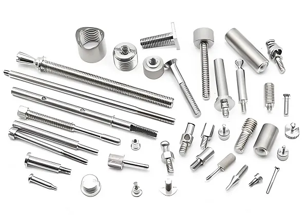
3. Swiss Machining (Best for Small, Complex Parts)
- Process: Uses a sliding headstock to support long, thin parts (diameters 0.5-32mm) during machining, preventing deflection. Ideal for micro-components with tight tolerances.
- Applications: Medical needles, watch parts, and small electrical connectors. A Swiss-machined brass pin (1mm diameter × 20mm length) achieved ±0.001mm tolerance and Ra 0.05μm finish.
- Advantages: Handles small diameters with minimal vibration, integrates turning and milling in one setup.
Step 4: Set Up & Machining
Proper setup ensures consistent quality and efficiency—calibrating tools, fixturing the material, and verifying program accuracy before full production.
Setup Procedures:
- Tool calibration: Use tool setters to measure tool length and diameter (±0.001mm accuracy), storing offsets in the machine controller to prevent collisions and ensure dimension accuracy.
- Workholding: Secure material with fixtures (vices, chucks, or custom jigs) that minimize movement during cutting. For irregular shapes, 3D-printed soft jaws or vacuum clamping provide uniform pressure without distortion.
- First-part inspection: Run a test part and verify critical dimensions with calipers, micrometers, or CMM (Coordinate Measuring Machine) before full production—catching programming errors or tool offsets early.
Machining Parameters:
- Cutting speed: Adjust based on material (100-300m/min for aluminum, 50-150m/min for steel) to balance tool life and cycle time.
- Feed rate: Control chip load (0.1-0.3mm per tooth) to prevent tool overload—higher rates for roughing, lower rates for finishing.
- Coolant: Flood or mist coolant removes chips and reduces heat (critical for titanium, which can gall without proper cooling).
Step 5: Post-Processing & Finishing
After machining, parts often require additional treatments to enhance functionality, appearance, or durability.
- Deburring: Remove sharp edges and burrs (≤0.01mm) using tumbling, brushing, or electrochemical deburring—critical for safety and assembly fit.
- Heat treatment: Harden steel parts (e.g., 4140 steel to 35-45 HRC) for wear resistance, or anneal aluminum to reduce residual stress and prevent warping.
- Surface coating: Apply anodizing (aluminum), plating (chrome/zinc for steel), or powder coating to improve corrosion resistance (1,000+ hours salt spray) and aesthetics.
- Assembly features: Add threads (cut or rolled), inserts, or hinges to prepare parts for final assembly—ensuring compatibility with mating components.
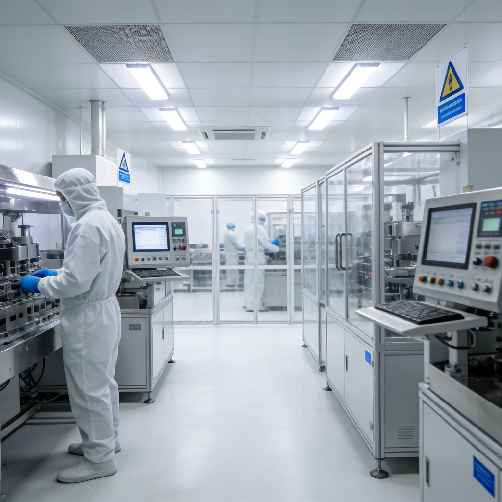
Step 6: Quality Control & Inspection
Rigorous inspection ensures every CNC part meets specifications, with statistical process control (SPC) to maintain consistency across production runs.
Inspection Methods:
- Dimensional checks: Use CMMs with 5-axis probes to verify 1000+ data points on complex parts, comparing results to CAD models with ±0.001mm accuracy.
- Surface finish testing: Profilometers measure Ra and Rz values to ensure functional performance (e.g., Ra 0.05μm for hydraulic seals to minimize friction).
- Material verification: Use spectrometers to confirm material composition (e.g., ensuring 316L stainless steel meets 16-18% chromium content).
- Functional testing: Validate part performance (e.g., pressure testing for fluid-carrying components, load testing for structural brackets).
Common Challenges & Solutions in CNC Machining
- Tool wear: Use carbide or diamond tools for abrasive materials (e.g., titanium), and implement tool life monitoring to replace tools before dimensional drift (>0.002mm).
- Part warping: Use stress-relief annealing, low-cutting-force parameters, and rigid fixturing to reduce distortion in thin-walled parts (≤2mm thickness).
- Surface finish defects: Adjust feed rates (slower for finishing), use sharp tools, and ensure proper coolant flow to eliminate chatter marks or built-up edge.
Why Partner with Goldcattle for CNC Parts?
Goldcattle’s CNC expertise delivers:
- Multi-axis capabilities (3-5 axis milling, turning, Swiss machining) for complex parts.
- Material-specific programming (optimized parameters for aluminum, steel, titanium).
- Rapid turnaround (2-3 days for prototypes, 2-4 weeks for production runs).
Upload your CAD files or part requirements via our online form to receive a free DFM analysis, material recommendation, and quote within 24 hours. Let’s transform your design into precision CNC parts.
“Goldcattle’s 5-axis CNC machining produced our aerospace component with ±0.003mm tolerance—their attention to toolpath optimization and in-process inspection eliminated rework, meeting our tight deadline.” — Aerospace OEM Client