1. Preparation Before Alignment (Safety & Tools)
1.1 Equipment Safety Check
- Machine Zero Return: Execute
G28 U0 W0(for CNC lathes) orG28 X0 Y0 Z0(for milling machines) to ensure the machine coordinate system is reset and avoid reference offset. - Workpiece Clamping: Inspect the clamping force of chucks/fixtures; use a dial indicator to check that workpiece radial/end face runout ≤ 0.02mm (≤ 0.005mm for high-precision machining).
- Spindle Status: Run the spindle idly for 30 seconds to confirm no abnormal noise; set the speed in line with tool requirements (e.g., 800-1200rpm for edge finders).
1.2 Tool List (Selected by Precision Requirements)
| Tool Type | Application Scenario | Precision Range |
|---|---|---|
| Ordinary Test Cutting Tool | Rough machining, no precision tools available | ±0.05mm |
| Photoelectric Edge Finder | Milling machines/ machining centers, regular workpieces | ±0.005-0.01mm |
| Dial Indicator (with magnetic base) | Special-shaped workpieces, high-precision positioning | ±0.002-0.005mm |
| Z-axis Setter (Tool Setter) | Precise Z-axis origin positioning | ±0.001mm |
| Caliper/Micrometer | Dimensional measurement verification | 0.01mm/0.001mm |
2. Core Alignment Methods (Detailed by Scenario)
Method 1: Test Cutting Method (No Precision Tools, Basic & Universal)
Applicable Equipment: CNC lathes, milling machines (when no edge finder is available)
Operation Steps (taking lathe X/Z axes as examples):
-
X-axis Origin Alignment
- Manually move the spindle near the workpiece outer circle and start the spindle (speed: 800-1000rpm).
- Manually feed the tool to lightly cut the workpiece outer circle (cutting depth: 0.1-0.2mm), then stop the spindle.
- Manually retract the tool (retract Z-axis away from the workpiece, keep X-axis stationary), and measure the workpiece outer circle diameter
Dwith a caliper. - Enter the workpiece coordinate system interface (e.g., G54) and input
X=-D/2(for diameter programming; inputX=-Dfor radius programming).
-
Z-axis Origin Alignment
- Manually move the tool near the workpiece end face, start the spindle, and lightly cut the end face (cutting depth: 0.1mm).
- Stop the spindle and manually retract the tool (retract X-axis away from the workpiece, keep Z-axis stationary).
- Enter the G54 interface and input
Z=0(take the cut end face as the Z-axis origin).
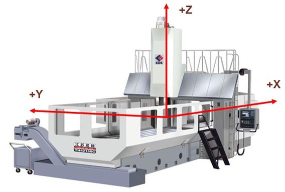
Note: For milling machines, align X/Y/Z axes separately. The Y-axis operation is the same as the X-axis—cut the workpiece side, then measure the width to calculate the origin.
Method 2: Photoelectric Edge Finder Method (Milling Machines/Machining Centers, Medium-High Precision)
Operation Steps:
- Install the Edge Finder: Clamp the edge finder in the tool holder and set the spindle speed to 800-1200rpm (avoid high speed to prevent damage).
- X-axis Alignment
- Manually move the Z-axis to bring the lower end of the edge finder close to the workpiece upper surface (distance: 5-10mm).
- Manually move the X-axis to make the edge finder probe lightly touch the left side of the workpiece until the edge finder light turns on; record the machine coordinate
X1. - Move the X-axis in the reverse direction, lightly touch the right side of the workpiece, and record the machine coordinate
X2. - Calculate the X-axis origin:
X0=(X1+X2)/2, and input it into the X parameter of G54.
- Y-axis Alignment: Repeat the X-axis steps, touch the front and rear sides of the workpiece, record
Y1/Y2, calculateY0=(Y1+Y2)/2, and input it. - Z-axis Alignment: Replace with a Z-axis setter, place the setter on the workpiece, manually lower the Z-axis until the setter light turns on, record
Z1, and inputZ=Z1 - setter height(e.g., if the setter height is 10mm, inputZ=-10).
Method 3: Dial Indicator Method (Special-Shaped Workpieces/High-Precision Workpieces, ≤ 0.005mm Precision)
Operation Steps:
- Install the Dial Indicator: Fix the magnetic base on the spindle, point the dial indicator probe vertically at the workpiece datum surface (e.g., outer circle/end face), and preload 0.1-0.2mm.
- Radial Alignment (X/Y Axes)
- Manually rotate the spindle, observe the dial indicator pointer swing, and record the maximum reading
Maxand minimum readingMin. - If
Max-Min > 0.005mm, fine-tune the workpiece (tap the fixture/adjust the center pin) until the runout difference ≤ 0.005mm. - Move the spindle to the position where the dial indicator pointer points to “0”, record the machine coordinate, and input it into the corresponding axis parameter of G54.
- Manually rotate the spindle, observe the dial indicator pointer swing, and record the maximum reading
- End Face Alignment (Z-axis): Point the dial indicator probe vertically at the workpiece end face, rotate the spindle, adjust the workpiece to make the end face runout ≤ 0.003mm, and set the lowest point of the end face as Z=0.
3. Operation Paths for Different CNC Systems (Key Step Differences)
| System Model | Workpiece Coordinate System Setting Entry | Parameter Input Steps |
|---|---|---|
| FANUC 0i/31i | Press the OFFSET SETTING key → Select “Workpiece Coordinate System” |
Move the cursor to G54-X/Y/Z, input the value directly, and press INPUT. |
| SIEMENS 828D | Click “Machining” → “Workpiece” → “Workpiece Coordinate System” | Select “G54”, input the calculated origin coordinates, and click “Confirm”. |
| MITSUBISHI M70 | Press the WORK OFFSET key → Switch to the “G54” page |
Input the value and press ENTER; the system saves automatically. |
| Huazhong HNC-210B | Click “Parameters” → “Workpiece Coordinates” | Select G54, input X/Y/Z values, and press the “Save” key. |
4. Post-Alignment Verification & Precision Control
4.1 Verification Steps
- Dry Run Verification: Write a test program (e.g.,
G54 G00 X0 Y0 Z5; G01 Z-1 F100; G00 Z5), disable Z-axis feed (or raise the Z-axis to a safe height), execute the program, and observe whether the trajectory fits the workpiece boundary. - Test Cutting Verification: Machine a 10mm×10mm shallow groove (or turn a 10mm-long outer circle), measure the dimension with a micrometer; the deviation must be ≤ 0.02mm (≤ 0.005mm for high-precision machining).
4.2 Common Problems & Solutions
| Problem Phenomenon | Cause Analysis | Solution |
|---|---|---|
| Reversed positive/negative of origin offset value | Measurement direction is opposite to the machine coordinate direction | Confirm the machine coordinate “+/-” direction (e.g., X-axis away from the origin is positive; X1 is negative when cutting the left side), and recalculate if necessary. |
| Large test cutting dimension deviation (> 0.05mm) | Edge finder/dial indicator not calibrated | Calibrate the edge finder with a standard block (e.g., for a 10mm standard block, the edge finder display should be 10±0.001mm). |
| Invalid coordinate system call | G54/G55 not specified in the program | Add G54 in the first line of the program (e.g., O0001 G54 G90 G00 X0 Y0). |
5. Precision Optimization Tips
- Multiple Measurements for Average Value: For the edge finder method, repeat measurements 2-3 times and take the average of X1/X2 to reduce random errors.
- Environmental Control: During high-precision alignment, avoid vibration around the machine (e.g., keep away from punch presses) and maintain the ambient temperature at 20±2℃ (temperature changes cause workpiece thermal deformation).
- Tool Maintenance: Regularly clean the edge finder probe (no oil contamination) and calibrate the dial indicator (once a year) to ensure tool precision.