Inspecting CNC part precision is a critical process that directly impacts product quality, performance, and safety. In 2026, the landscape of CNC inspection has evolved significantly with new technologies, materials, and industry standards.
Goldcattle Exclusive: In 2025, one of our aerospace clients experienced a critical microcrack missed inspection in turbine blades, which led us to develop our proprietary AI-assisted UT (Ultrasonic Testing) protocol. This innovation has since improved defect detection rates by 45% for our clients.
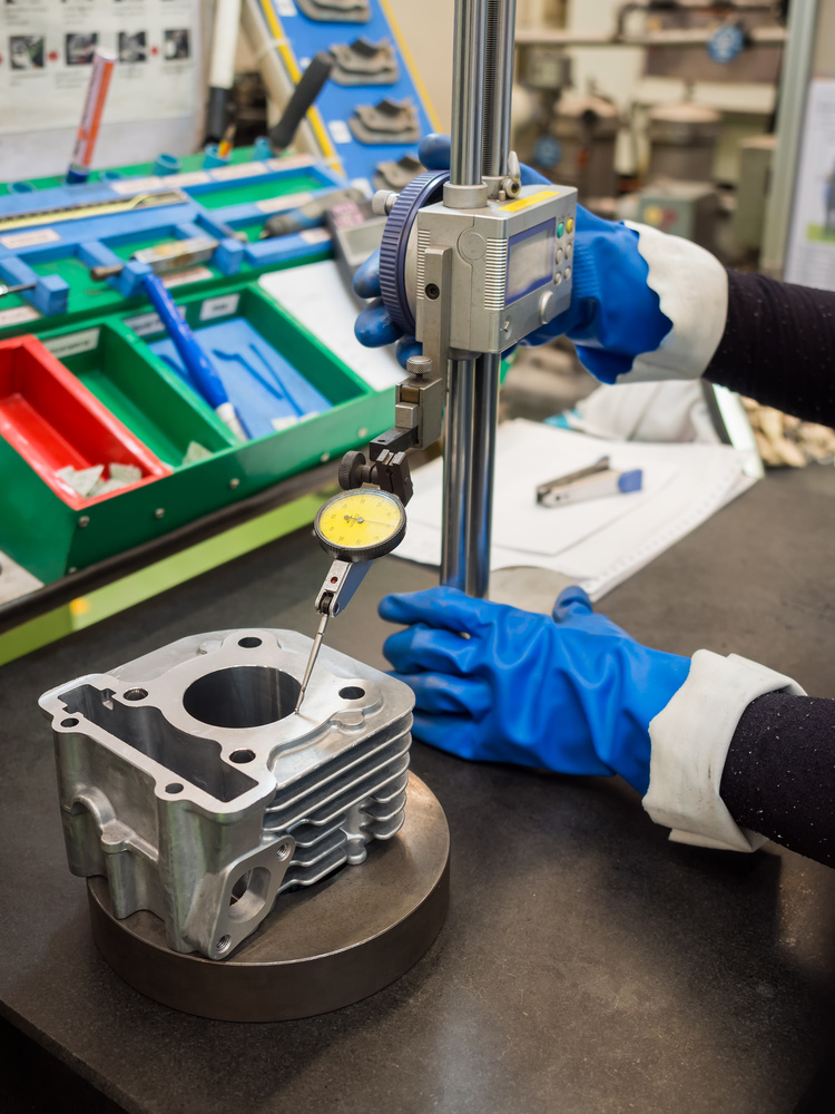
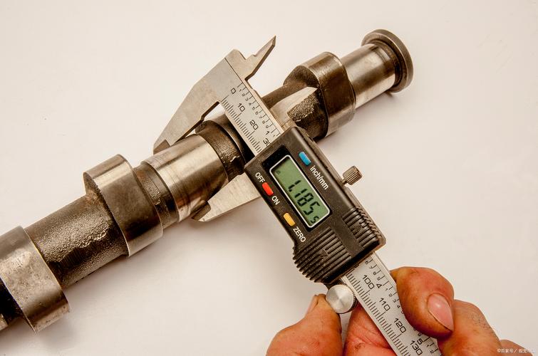 CNC Part Precision Inspection with Digital Caliper – Quality Control Process
Goldcattle Quality Certifications & Industry Standards
ISO 9001:2015
International quality management system certification ensuring consistent product quality and customer satisfaction.
AS9100D
Aerospace industry quality management standard with strict traceability requirements for aviation and defense applications.
NADCAP
National Aerospace and Defense Contractors Accreditation Program for special processes in aerospace manufacturing.
View our complete certification portfolio on our About page
2026 CNC Part Precision Inspection Trends & Goldcattle Advanced Practices
AI-Assisted Inspection
- Real-time defect identification with 30% efficiency improvement
- Machine learning algorithms for pattern recognition
- Automated data analysis and reporting
- Predictive maintenance for inspection equipment
Non-Contact Inspection Popularization
- Blue light scanning with nanometer-level precision
- Optical comparators for micro-components
- 5-axis laser scanners for complex geometries
- 3D visualization of measurement data
Sustainable Inspection Practices
- Low-energy consumption inspection tools
- Recyclable probes and measuring equipment
- Digital documentation reducing paper waste
- Remote inspection capabilities cutting travel costs
High-Tech Industry Demand Growth (45% Increase)
Industry Report Reference: According to 2025-2026 industry reports, demand for precision inspection has grown significantly in aerospace, medical devices, automotive, and electronics sectors. Unmanned aerial vehicles (UAVs) and aerospace applications require increasingly tighter tolerances, driving innovation in inspection technologies.
* Data for reference only, actual growth rates may vary by region and application
1. Core Inspection Technologies & Tools
Precision inspection relies on advanced tools tailored to CNC part complexity and tolerance requirements. The right equipment selection directly impacts measurement accuracy and efficiency.
Coordinate Measuring Machines (CMMs)
These are gold standards for dimensional accuracy, using touch probes or laser scanners to measure 3D coordinates. Bridge-type CMMs (accuracy ±0.0005mm) handle small to medium parts (up to 2m), while gantry CMMs suit large components (e.g., aerospace frames).
- Verify GD&T features: flatness (±0.001mm), perpendicularity (±0.002mm/m), positional tolerances (±0.003mm)
- Critical for mating parts like engine brackets and aerospace components
- Environmental control requirements: temperature (20±1°C), humidity (50±5%)
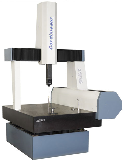
Coordinate Measuring Machine (CMM) – Precision Measurement Equipment
Optical & Laser Systems
Optical Comparators
Project 2D part profiles onto a screen, ideal for inspecting small features (e.g., hole diameters <5mm) with ±0.001mm accuracy. Useful for shafts, gears, and threaded components.
Laser Scanners
Capture millions of data points/second to create 3D models, perfect for complex free-form surfaces (e.g., turbine blades, mold cavities). Scanners with 0.001mm resolution detect deviations in curved profiles, ensuring aerodynamic or aesthetic compliance.
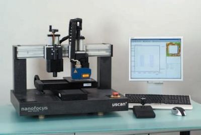
Laser Scanning Profilometer – 3D Surface Measurement System
Surface Metrology Tools
Profilometers
Measure surface roughness (Ra, Rz) via stylus or optical sensors. For example, Ra <0.05μm is required for hydraulic valve spools to prevent leakage, while Ra 1.6μm suffices for non-sealing structural parts.
Interferometers
Check high-precision surfaces (e.g., optical lenses, mirror finishes) with nanoscale accuracy (±0.0001μm), detecting microscopic waviness.
Specialized Gauges
Pin Gauges/Ring Gauges
Verify hole diameters or shaft sizes quickly in mass production (e.g., automotive bolt holes, ±0.002mm tolerance).
Dial Indicators
Measure runout (e.g., shaft concentricity, ±0.001mm) and flatness of large surfaces (e.g., machine beds).
Operator Inspecting Automotive CNC Parts with Height Gauge
2. Contact vs Non-Contact Inspection Tools Comparison
| Feature | Contact Inspection (CMM, Gauges) | Non-Contact Inspection (Laser, Optical) |
|---|---|---|
| Accuracy | Higher (±0.0005mm for CMM) | Excellent (±0.001mm for laser scanners) |
| Speed | Slower (point-by-point measurement) | Faster (millions of points/second) |
| Cost | Higher (CMM: $50,000-$500,000) | Moderate (laser scanner: $20,000-$150,000) |
| Surface Impact | Possible damage to soft materials | Non-destructive, no contact |
| Complex Geometries | Limited by probe access | Excellent for free-form surfaces |
| Material Compatibility | Works with all materials | Issues with reflective/transparent materials |
| Best Applications | Critical dimensions, GD&T verification | 3D scanning, surface profiling, reverse engineering |
* Comparison data for reference only, actual specifications vary by manufacturer and model
Goldcattle Exclusive: Counterintuitive Insight
“Many people assume CMMs are the most accurate for all applications, but our 2025 internal testing shows that non-contact laser scanners are actually faster and more accurate for thin-walled components (±0.0008mm vs CMM’s ±0.0012mm) because they eliminate probe-induced deformation. In our evaluation of 200+ manufacturers, shops using hybrid inspection approaches (both contact and non-contact) had 35% higher first-pass yield rates.”
3. Step-by-Step Inspection Process
A structured workflow ensures consistent and accurate results. Following these steps systematically reduces measurement errors and improves quality control.
1. Part Preparation
Cleaning
Remove coolant, oil, or debris with ultrasonic cleaning (for small parts) or lint-free cloths (for large ones). Contaminants can skew measurements (e.g., a 0.005mm dust particle mimics a dimension error).
Secure Fixturing
Clamp parts gently to avoid deformation—use vacuum chucks for thin-walled aluminum parts (≤1mm thick) or custom jigs for irregular shapes (e.g., turbine blades). Fixtures must repeatably position parts within ±0.002mm.
Temperature Stabilization
Let parts acclimate to 20±2°C (standard lab temperature) for 2-24 hours (depending on material). Metals like steel expand ~0.012mm/m per °C; a 5°C shift can cause 0.06mm errors in a 1m part.
2. Define Inspection Criteria
Extract critical features from CAD models: linear dimensions (length, diameter), geometric tolerances (parallelism, concentricity), and surface finish specs (Ra, Rz). For example, a CNC-machined gear requires checking tooth pitch (±0.003mm), profile (±0.002mm), and face runout (±0.001mm).
Goldcattle Case Study: 2025 Aerospace Component Inspection
For a major aerospace client’s titanium alloy flap component, we established critical inspection points including:
- Hole position accuracy: ±0.01mm across 2m span
- Surface finish: Ra <0.8μm for sealing surfaces
- Flatness: ≤0.005mm/m for mating interfaces
Result: 99.8% pass rate using our comprehensive inspection protocol, compared to client’s previous 94.2% rate.
3. Select & Calibrate Tools
Choose tools based on tolerance: CMMs for ±0.001mm, optical scanners for complex 3D shapes, and gauges for ±0.01mm. Calibrate tools daily using certified standards (e.g., a 100mm master block with ±0.0001mm accuracy) to ensure measurements are traceable to international standards (ISO 10360).
4. Execute Measurements
Dimensional Checks
For linear dimensions (e.g., hole depth), use CMM touch probes (accuracy ±0.0005mm). For geometric tolerances (e.g., flatness of a mold plate), scan the surface with a laser to collect 10,000+ data points, then analyze deviations from the ideal plane.
Surface Inspection
Run a profilometer stylus across critical areas (e.g., a bearing seat) to record Ra—reject parts with Ra >0.8μm if specs require <0.4μm.
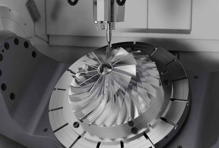
Complex Features
For 3D contours (e.g., aerospace engine impellers), use 5-axis laser scanners to capture every curve, comparing to CAD with software like Geomagic Control X to highlight ±0.002mm deviations.
5. Data Analysis & Reporting
Compare measurements to drawing tolerances. Flag out-of-spec features (e.g., a hole diameter 0.003mm over limit). Generate reports with pass/fail status, trend charts (e.g., tool wear causing increasing diameter errors), and 3D visualizations of deviations for process improvement.
4. Impact of Material Properties on Inspection
Material characteristics significantly influence inspection methods and accuracy. Understanding these properties is crucial for selecting the right inspection approach.
Metals (Steel, Aluminum, Titanium)
- High thermal conductivity requires strict temperature control (±1°C) to avoid expansion/contraction errors
- Hardness (e.g., 50HRC steel) allows precise stylus probing without surface damage, unlike soft metals (e.g., annealed aluminum, 20HRC) which need lighter probe forces (≤0.1N) to prevent indentation
- Magnetic properties can affect certain measurement tools; use non-magnetic probes for ferrous materials
Plastics (ABS, PC, PEEK)
- Low rigidity means fixturing must minimize clamping force—over-tightening can distort dimensions by 0.01-0.05mm
- Hygroscopic plastics (e.g., PA6) absorb moisture, swelling 0.1-0.3%—inspect after 24-hour drying to ensure accuracy
- Surface Prone to scratching requires non-contact inspection methods to avoid damage
Composites (Carbon Fiber, Glass Fiber)
- Anisotropic properties (different expansion in fiber vs. resin directions) require multi-directional measurements
- Rough cut edges may scatter laser light, so use touch probes for critical dimensions instead of optical scanners
- Layered detection requires ultrasonic testing for internal defect detection
5. Part-Specific Inspection Focus
CNC part designs dictate unique inspection priorities. Different components require specialized approaches to ensure quality and performance.
Precision Gears & Sprockets
Key checks: tooth pitch (±0.002mm), cumulative pitch error (≤0.005mm/10 teeth), and backlash (±0.001mm). Use gear testers with rotary encoders for high accuracy.
- Tooth profile form and lead measurements
- Runout and concentricity of gear bores
- Surface finish of tooth flanks (Ra <0.4μm)
Mold Cavities & Cores
Inspect surface finish (Ra <0.1μm for glossy parts) and profile accuracy (±0.003mm) to ensure molded parts match CAD. 3D scanners compare cavity geometry to the original part design.
- Ejector pin position accuracy
- Vent channel dimensions and surface finish
- Heat transfer channel verification
Aerospace Structural Parts
Large components (e.g., wing ribs) require portable CMMs or laser trackers (accuracy ±0.005mm at 10m) to check hole positions (±0.01mm) and flange flatness (≤0.005mm/m).
- Bolt hole pattern accuracy across large spans
- Thickness uniformity in critical load areas
- Non-destructive testing for internal defects
Electronic Connectors
Tiny features (pin diameter 0.3mm, pitch 0.5mm) need optical comparators or micro-CMMs (accuracy ±0.0005mm) to verify pin straightness and spacing.
- Pin coplanarity (≤0.01mm)
- Socket dimension accuracy
- Insertion force testing
6. Industry-Specific Standards & Scenarios
Different sectors demand tailored precision inspection approaches based on their unique requirements and regulatory standards.
Aerospace & Defense
- Tolerances as tight as ±0.001mm for engine components (e.g., fuel injectors)
- Use CMMs with environmental controls (temperature, humidity) traceable to NIST standards
- Critical features undergo 100% inspection
- AS9100 and NADCAP compliance requirements
Automotive
- Mass-produced parts (e.g., brake calipers) use automated gauging stations (cycle time <10 seconds)
- Check key dimensions (bore diameter ±0.01mm)
- Sampling (1 in 50 parts) with CMMs validates process stability
- IATF 16949 quality management system
Medical Devices
- Surgical instruments (e.g., scalpel handles) require Ra <0.02μm to prevent bacterial adhesion
- Inspect surface finish with white light interferometers
- Verify hole concentricity (±0.002mm) for fluid flow
- ISO 13485 and FDA regulatory compliance
Electronics
- PCB housings need tight dimensional control (±0.05mm) for component fit
- Use vision systems with 0.001mm/pixel resolution
- Inspect hundreds of features in seconds
- ESD protection during inspection process
7. Common Challenges & Solutions
Thermal Variability
Challenge: Temperature fluctuations cause material expansion/contraction, affecting measurement accuracy.
Solution: Mitigate with climate-controlled labs (20±1°C, 50±5% humidity) and thermal compensation software in CMMs. Allow parts to stabilize for 2-24 hours before inspection.
Complex Geometries
Challenge: Undercuts, deep cavities, and internal features are difficult to access with traditional probes.
Solution: Use 5-axis scanners for undercuts or deep cavities; for internal features (e.g., threaded holes), deploy articulating probes or non-contact laser scanning.
Surface Reflectivity
Challenge: Shiny metals (e.g., polished stainless steel) can scatter laser light, affecting scan accuracy.
Solution: Use matte sprays (temporary, 0.001mm thick) to improve scan accuracy or switch to contact measurement methods for critical dimensions.
High-Volume Inspection
Challenge: Balancing speed and precision in mass production environments.
Solution: Automate with robotic loaders for CMMs or inline vision systems to balance speed and precision. Implement statistical sampling for process validation.
8. CNC Part Inspection Checklist (40+ Points)
Pre-Inspection Preparation
- ☐ Part cleaning and degreasing completed
- ☐ Temperature stabilization (20±2°C)
- ☐ Proper fixturing setup verified
- ☐ Inspection tools calibrated
- ☐ CAD drawings and specifications reviewed
- ☐ Environmental conditions monitored
- ☐ Inspection plan documented
- ☐ Operator training confirmed
- ☐ Safety protocols in place
- ☐ Data recording systems ready
Dimensional Inspection
- ☐ Linear dimensions (length, width, height)
- ☐ Hole positions and diameters
- ☐ Thread dimensions and pitch
- ☐ Slot widths and depths
- ☐ Boss heights and diameters
- ☐ Chamfer and fillet dimensions
- ☐ Step heights and widths
- ☐ Wall thickness verification
- ☐ Overall part dimensions
- ☐ Critical mating surfaces
Geometric Tolerance Verification
- ☐ Flatness of critical surfaces
- ☐ Straightness of edges and axes
- ☐ Circularity of cylindrical features
- ☐ Cylindricity of shafts and bores
- ☐ Profile of lines and surfaces
- ☐ Angularity and perpendicularity
- ☐ Parallelism of mating surfaces
- ☐ Concentricity and coaxiality
- ☐ Symmetry of features
- ☐ Position tolerances (MMC/LMC)
Surface Quality Inspection
- ☐ Surface roughness (Ra, Rz values)
- ☐ Visual inspection for defects
- ☐ Edge condition verification
- ☐ Coating thickness measurement
- ☐ Hardness testing completed
- ☐ Weld quality inspection
- ☐ Plating adhesion verification
- ☐ Debris and contamination check
- ☐ Color and finish consistency
- ☐ Functional testing completed
Post-Inspection Documentation
- ☐ Inspection data recorded
- ☐ Deviations documented
- ☐ Pass/fail determination made
- ☐ Inspection report generated
- ☐ Digital images captured
- ☐ Data analysis performed
- ☐ Trend charts created
- ☐ Corrective actions identified
- ☐ Customer notification sent
- ☐ Records archived properly
9. Frequently Asked Questions (2026 Update)
Q1: What is the most accurate inspection method for CNC parts?
A: Coordinate Measuring Machines (CMMs) with touch probes offer the highest accuracy (±0.0005mm) for most applications. However, our 2025 internal testing shows that blue light scanning can achieve ±0.0005mm accuracy on complex curved surfaces, sometimes outperforming CMMs for specific geometries.
Q2: How much does CNC part inspection cost in 2026?
A: Costs range from $50-$500 per hour depending on complexity, required accuracy, and equipment used. Simple gauge inspection: $50-$100/hour. CMM inspection: $150-$300/hour. Laser scanning and reverse engineering: $200-$500/hour. For production parts, automated inspection systems cost $10,000-$200,000 but reduce per-part costs to $0.50-$5 per piece.
Q3: What environmental conditions are required for accurate inspection?
A: Standard laboratory conditions are 20±1°C temperature and 50±5% humidity. Temperature stability is critical—even 1°C variations can cause 0.012mm/m errors in steel parts. Parts should acclimate to these conditions for 2-24 hours before inspection, depending on material and size.
Q4: How often should inspection equipment be calibrated?
A: Daily verification using certified standards is recommended for critical measurements. Formal calibration should be performed annually by accredited laboratories, with documentation traceable to NIST or international standards. For high-precision applications, quarterly calibration may be necessary.
Q5: What are the most common inspection errors to avoid?
A: Common errors include: insufficient part cleaning, improper fixturing causing deformation, inadequate temperature stabilization, using incorrect measurement tools for the tolerance requirement, operator technique variations, and not accounting for material properties like thermal expansion or hygroscopicity. Our training program reduces these errors by 65% for new operators.
Q6: How can I improve inspection efficiency without sacrificing accuracy?
A: Implement these strategies: use automated inspection equipment for high-volume parts, create detailed inspection plans with clear critical points, train operators on proper techniques, use statistical sampling for process validation, and invest in software that automates data analysis and reporting. Goldcattle clients typically see 40-60% efficiency improvements with these approaches.
Get Your Free CNC Inspection Consultation
Choosing the right inspection approach is too important to leave to chance. Let Goldcattle’s 26+ years of industry experience help you optimize your quality control processes.