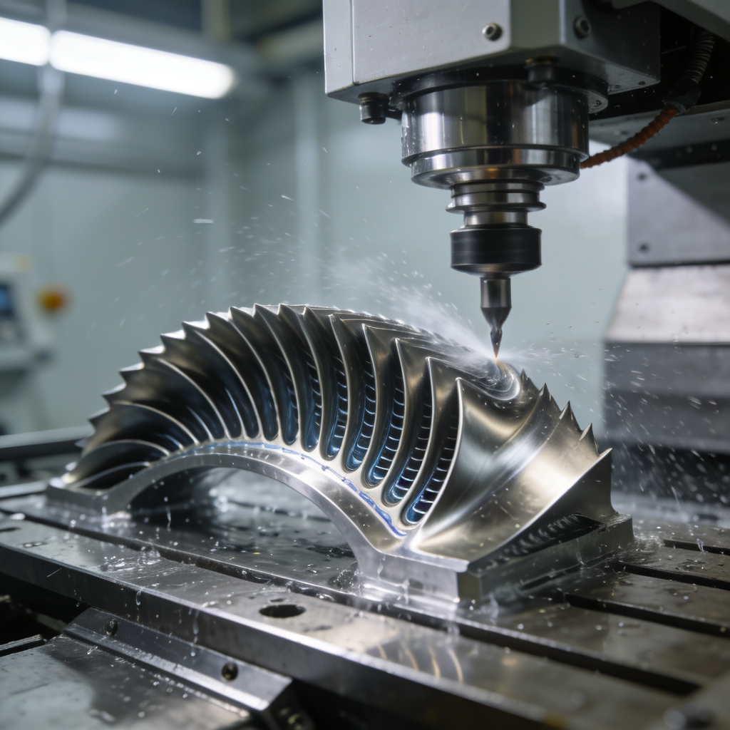
Circular interpolation is a core function of CNC machine tools, enabling precise machining of arcs, circles, and curved contours (e.g., bearing races, cam profiles, and rounded corners of mechanical parts). Incorrect G-code programming for circular interpolation often leads to dimensional errors (tolerance >±0.02mm), tool path deviations, or even machine collisions. This article systematically explains the types of circular interpolation G-codes, programming rules, parameter setting, and error correction methods, combined with practical examples and schematic diagrams, to help engineers master high-precision circular interpolation programming.
Core Concepts: What is CNC Circular Interpolation & Its G-code Basics?
Q&A: What are the key G-codes and principles of circular interpolation?
Circular interpolation refers to the CNC system controlling the machine tool axes to move along a preset circular path at a constant feed rate, divided into clockwise (G02) and counterclockwise (G03) directions (determined by viewing the non-interpolation axis from the positive direction to the negative direction). The core G-code specifications are as follows:
|
Interpolation Type
|
G-code
|
Applicable Planes
|
Programming Formats
|
|
Clockwise Circular Interpolation
|
G02
|
X-Y (G17), X-Z (G18), Y-Z (G19)
|
G02 X__ Y__ I__ J__ F__; (center coordinate mode) G02 X__ Y__ R__ F__; (radius mode)
|
|
Counterclockwise Circular Interpolation
|
G03
|
X-Y (G17), X-Z (G18), Y-Z (G19)
|
G03 X__ Y__ I__ J__ F__; (center coordinate mode) G03 X__ Y__ R__ F__; (radius mode)
|
Key parameter definitions:
- X/Y/Z: End coordinates of the arc (absolute coordinates with G90, incremental coordinates with G91);
- I/J/K: Incremental values from the arc start point to the center point (I for X-axis, J for Y-axis, K for Z-axis; positive/negative based on axis direction);
- R: Arc radius (R>0 for arcs ≤180°, R<0 for arcs >180°);
- F: Feed rate (mm/min for linear axes, mm/r for rotary axes).
Core pain points in traditional programming:
- Confusion between I/J/K and R modes leads to arc center offset (error >0.05mm);
- Ignoring plane selection (G17/G18/G19) causes interpolation in wrong planes, resulting in scrapped parts;
- Improper feed rate setting leads to uneven cutting (surface roughness Ra>3.2μm) or tool vibration.
Advantages of standardized programming:
- Center coordinate mode (I/J/K) achieves arc accuracy ±0.005mm, suitable for high-precision circular parts (e.g., hydraulic valve spools);
- Radius mode simplifies programming for small arcs (≤180°), reducing code length by 40% and programming time by 30%.
Programming Steps: How to Write High-Precision Circular Interpolation G-code?
1. Preparatory Work: Determine Interpolation Parameters
Step 1: Confirm Interpolation Plane and Direction
- Default plane: G17 (X-Y plane) for milling machines; switch to G18 (X-Z) or G19 (Y-Z) for lathes/vertical machining centers;
- Direction judgment: Take G17 (X-Y plane) as an example—looking from the positive Z-axis to the X-Y plane, clockwise movement uses G02, counterclockwise uses G03 (see Figure 1).
Step 2: Calculate Coordinates (Critical for Accuracy)
- Example 1: Machining a 100mm-diameter full circle in X-Y plane
Start point: (50, 0), center point: (0, 0), end point: (50, 0) (same as start point for full circle).
-
- Absolute coordinate programming (G90):
G90 G17 G00 X50.0 Y0.0; (Rapid positioning to start point)
G03 X50.0 Y0.0 I-50.0 J0.0 F100; (Counterclockwise full circle, I=-50.0 (X start – X center), J=0)
Radius mode is not recommended for full circles (system may recognize R=50 as 180° arc, leading to path error).
Step 3: Set Feed Rate and Tool Compensation
- Feed rate (F): 80–150mm/min for rough machining (arc depth >0.5mm), 30–80mm/min for finish machining (Ra≤1.6μm);
- Tool radius compensation (G41/G42): Add before interpolation (e.g., G41 X50.0 Y0.0 D01;) to avoid undercut/overcut (compensation value stored in tool offset register D01).
2. Two Programming Modes: I/J/K vs. R (Application Scenarios)
Mode 1: Center Coordinate Mode (I/J/K) – High Precision
- Applicable scenarios: Full circles, arcs >180°, high-precision parts (tolerance ±0.01mm);
- Programming rules: I/J/K are incremental values (not absolute coordinates of the center); for incremental programming (G91), I/J/K remain incremental relative to the start point.
- Error correction: If the arc is distorted, check if I/J/K signs are reversed (e.g., I=50 instead of I=-50 leads to center offset by 100mm).
Mode 2: Radius Mode (R) – Simplified Operation
- Applicable scenarios: Arcs ≤180°, simple contours (e.g., rounded corners R5/R10);
- Critical note: R is positive for arcs ≤180°, negative for arcs >180° (e.g., 270° arc: R=-50); using positive R for >180° arcs results in 180° arc machining (error >5mm).
3. Practical Example: Machining a R20 Rounded Corner (X-Y Plane)
Start point: (100, 50), end point: (80, 70), arc center: (80, 50), R=20 (arc ≤180°).
G90 G17 G00 X100.0 Y50.0; // Rapid positioning to start point
G41 X100.0 Y50.0 D01; // Tool radius compensation (D01=5mm)
G01 X80.0 Y50.0 F80; // Linear feed to arc start point
G02 X80.0 Y70.0 I-20.0 J0 F60; // Clockwise arc (I=-20, J=0)
G01 X100.0 Y70.0 F80; // Linear feed to exit arc
G40 X100.0 Y80.0; // Cancel tool compensation
Error Correction & Optimization: How to Ensure Circular Interpolation Precision?
1. Common Errors and Solutions
|
Error Type
|
Performance
|
Root Cause
|
Solution
|
|
Arc center offset
|
Arc radius deviation >0.03mm
|
I/J/K values calculated incorrectly (absolute vs. incremental confusion)
|
Use CAD to extract start/center/end coordinates; verify with machine tool coordinate display
|
|
Wrong interpolation direction
|
Arc is reversed (e.g., G02 instead of G03)
|
Direction judgment based on wrong plane
|
Mark plane and direction on engineering drawings; simulate with CAM software (e.g., MasterCAM)
|
|
Uneven arc surface
|
Ra>3.2μm, tool marks visible
|
Feed rate too high (>150mm/min) or spindle speed mismatch
|
Reduce F to 40–60mm/min; adjust spindle speed (S=1500–3000rpm for carbide tools)
|
|
Machine vibration during interpolation
|
Arc chatter marks, tool damage
|
Tool overhang >5×tool diameter; feed rate fluctuation
|
Shorten tool overhang; enable constant surface speed (G96 for lathes)
|
2. Advanced Optimization Techniques
Technique 1: CAM Simulation Verification
- Use MasterCAM/UG NX to simulate tool paths before machining, checking for:
-
- Arc continuity (no gaps between arc and linear segments);
-
- Tool interference (e.g., tool shank collision with workpiece for internal arcs);
-
- Parameter consistency (I/J/K/R match drawing dimensions).
Technique 2: Real-Time Parameter Adjustment
- Machine tool CNC systems (e.g., Fanuc 0i ) support real-time feed rate override (0–150%) via handwheel, adjusting F during finish machining to improve surface quality;
- Enable arc acceleration/deceleration control (parameter No. 1602 in Fanuc) to smooth feed rate changes at arc start/end (reduces corner error to ±0.002mm).
Technique 3: Post-Processing Inspection
- Use a dial indicator (accuracy ±0.001mm) to measure arc radius and roundness after machining;
- For critical parts (e.g., aerospace bearing seats), use a roundness measuring instrument to verify roundness error ≤0.003mm.
Application Cases: Circular Interpolation in Different CNC Machine Tools
Case 1: CNC Lathe (X-Z Plane, G18) – Machining a Φ50mm Arc Shaft
G90 G54 G00 X55.0 Z5.0; // Rapid positioning
S2000 M03; // Spindle speed 2000rpm, clockwise
G42 X50.0 Z0.0 T0101 F100; // Tool nose radius compensation (T0101)
G03 X50.0 Z-30.0 I0 K-15.0 F80; // Counterclockwise arc (R15, X-Z plane)
G01 Z-50.0 F100; // Linear turning
G40 X55.0 Z5.0; // Cancel compensation
M05; // Spindle stop
M30; // Program end
Case 2: CNC Milling Machine (X-Y Plane, G17) – Machining a Φ80mm Circular Groove
G90 G54 G00 X40.0 Y0.0 Z5.0; // Rapid positioning
S3000 M03; // Spindle speed 3000rpm
G01 Z-5.0 F50; // Z-axis feed to groove depth
G02 X40.0 Y0.0 I-40.0 J0 F60; // Clockwise full circle groove (Φ80)
G00 Z50.0; // Z-axis rapid retract
M05;
M30;
Key Considerations for Mastering Circular Interpolation
- Parameter clarity: Distinguish absolute/incremental coordinates (G90/G91) and I/J/K incremental rules to avoid center offset;
- Plane selection: Confirm G17/G18/G19 before programming (critical for multi-axis machines);
- Simulation first: Always simulate tool paths via CAM/CNC system to detect errors before machining;
- Tool compensation: Correctly use G41/G42 (left/right compensation) to avoid undercut/overcut for arc contours;
- Equipment calibration: Regularly calibrate machine tool backlash (≤0.002mm) and spindle runout (≤0.001mm) to ensure interpolation precision.
Conclusion
Mastering G-code programming for CNC circular interpolation is crucial for precise curved part machining. Following plane selection rules, accurate parameter calculations, and error correction can reduce arc machining errors to ±0.005mm, surface roughness to Ra≤0.8μm, and part rejection rates by 80%. In aerospace, automotive, and mold manufacturing—industries with common curved contours—standardized programming boosts machining efficiency by 50% and ensures consistent quality. With CAM simulation and real-time adjustments, CNC circular interpolation remains a key precision manufacturing skill, enabling the production of complex, high-performance parts.
(Contact us now for customized G-code programming training and CNC machining process optimization solutions!)