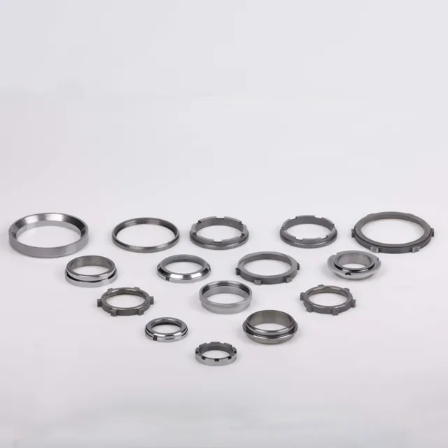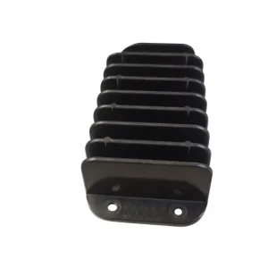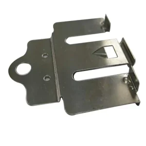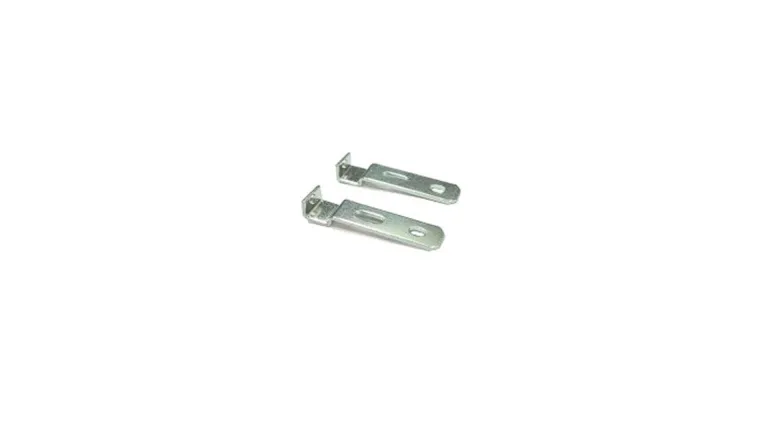
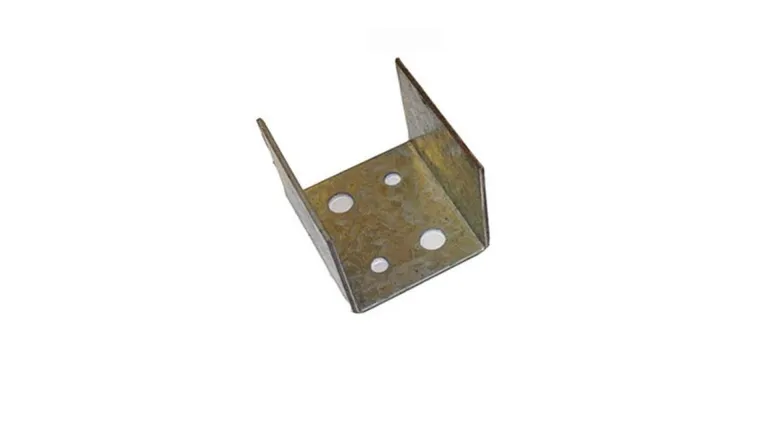
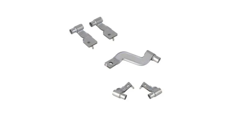
Custom CNC Machined Precision Metal Parts – High Accuracy Components

Place of origin :  XiaMen, China

Brand name : JSD

Model : MS-10

Material : Stainless steel, copper, iron

Type : OEM

Application : Industrial equipment

Color : Customizable

Process : Laser Cutting Bending Stamping

Service : Customized Processing Service

Technology : 24 years experience

Size : Customized

Drawing Format : 3D/CAD/DWG//STEP/PDF

Description

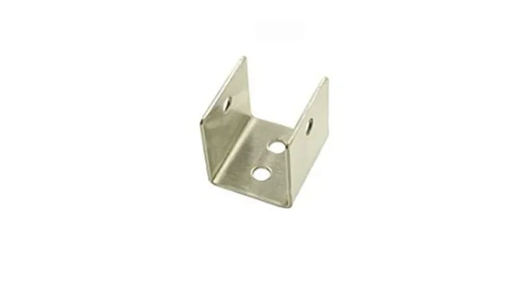
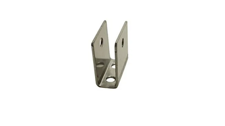
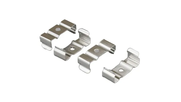
Stainless Steel U-Shaped Stamping Bracket — Custom OEM Sheet Metal Manufacturing

A corrosion-resistant structural fixing component produced through laser cutting, precision bending, and stamping — designed for industrial mounting, support, and alignment applications where long-term exposure to moisture or chemicals is expected.

Tolerance ±0.05 mm
MOQ from 100 pcs
Lead Time 7–15 Days
OEM / ODM Supported
Stainless steel U-shaped stamping bracket — corrosion-resistant industrial fixing component

Quick Specs — Purchasing Decision Reference

Material Grade
SS201 / 304 / 316 / Copper / Iron
Thickness Range
0.5 – 6.0 mm
Dimensional Tolerance
±0.05 – ±0.1 mm
Production Process
Laser cutting + bending + stamping
Tooling Type
Progressive die / single-operation die
Max Press Capacity
Up to 200T
Surface Finish
Passivation / Polishing / Powder coating
Drawing Format
CAD / STEP / PDF / DWG / IGES
Customization
Full — geometry, holes, thickness, finish
Quality System
ISO 9001 certified

Functional Role & Engineering Context

A U-shaped stamping bracket serves as a structural interface between a component and its mounting surface — securing position, absorbing load, and maintaining alignment under vibration or thermal cycling. The U-form geometry provides two parallel flanges that distribute clamping force across a wider contact area than a flat plate, reducing localized stress concentration on the mounted assembly.

In corrosive service environments — marine installations, chemical processing plants, outdoor enclosures — the material selection shifts from carbon steel to austenitic stainless (304 for general corrosion resistance, 316 where chloride exposure is present). The stamping process preserves material grain structure without the thermal distortion introduced by welding-based fabrication.

Key distinction: Stamped brackets achieve dimensional consistency across production volumes because the die defines the final shape — unlike welded brackets where each joint introduces variability in alignment, fillet quality, and heat-distortion zone geometry.

U-shaped stainless steel bracket showing parallel flanges and bending geometry

Stamped Bracket vs. Welded Bracket — Manufacturing Comparison
Criteria Stamped (Die-formed) Welded (Fabricated)
Dimensional Consistency Die-defined — batch repeatability ±0.05 mm Joint-dependent — variance from weld distortion
Production Speed Progressive die: 30–60 strokes/min Manual or robotic — 3–10 min per part
Material Integrity Grain structure preserved — no thermal zone Heat-affected zone near weld reduces local strength
Cost at Volume Lower per unit — die amortization over 10K+ pcs Higher — labor and consumables scale linearly
Corrosion Resistance Uniform — continuous surface, no crevice at joints Crevice risk at weld seams — requires post-weld passivation
Geometry Complexity Limited to formable shapes — bends, flanges, draws Flexible — can join dissimilar sections and 3D frameworks
Best Use Case Brackets, clips, U/L/Z shapes at 500+ quantity Large frames, multi-member assemblies, low-volume custom

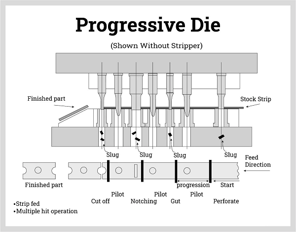
Metal stamping press operation — progressive die forming sheet metal bracket

Stamping Manufacturing Capability

Xiamen Goldcattle operates stamping presses from 30T to 200T, configured for both single-operation and progressive die production. Tooling is designed and maintained in-house — reducing lead time for die modification and enabling rapid iteration during prototype-to-production transitions.

Press Tonnage Range
30T – 200T mechanical and hydraulic presses, covering thin-gauge clips through heavy structural brackets.
Progressive Die Capability
Multi-station progressive dies for high-volume runs — blanking, forming, and piercing in one stroke sequence.
In-House Tooling
Die design, fabrication, and maintenance under one roof — direct engineering control over tool geometry and wear replacement.
Tolerance Control
±0.05 mm on formed dimensions, ±0.1 mm on bend angles. Die repeatability verified through first-piece and periodic sampling.
Batch Production Scale
100-piece minimum for custom dies; 50K+ monthly capacity on progressive die programs. Prototype samples before full run commitment.
Combined Processes
Laser cutting + stamping + bending in one workflow — no outsourcing gaps between blanking and forming stages.

Production Workflow — From Drawing to Verified Bracket

Drawing Review
Die Design
Laser Cutting
Stamping + Bending
Deburring
Surface Treatment
Dimensional QC
Pack & Ship

Drawing Review → Die Design

Engineering evaluates bend sequence, springback compensation, and hole placement relative to bend lines. Progressive die stations are mapped before any steel is cut — reducing iteration cycles on first articles.

Stamping + Bending → Deburring

The core forming stage. Laser-cut blank enters the press; die operations form the U-profile in one stroke sequence. Deburring removes all stamping edges before surface treatment, ensuring coating adhesion on clean surfaces.

Surface Treatment → Dimensional QC

Finish applied per specification (passivation, coating, etc.). Final dimensional verification occurs after treatment — confirming that plating thickness or coating buildup does not push features outside tolerance.

Material Selection — Grade-by-Application Guide

Bracket material is selected based on the service environment, not just availability. The grade determines corrosion resistance, formability during stamping, and long-term mechanical stability under load.

Grade Corrosion Level Formability Typical Application
SS201 Moderate — indoor / dry Good Interior equipment mounts, cost-sensitive consumer brackets
SS304 High — moisture / mild chemical Excellent Food processing, HVAC, electrical enclosures, general outdoor
SS316 Superior — chloride / marine Excellent Marine hardware, chemical plant, salt-exposure installations
Copper (C110) Low — decorative / conductive Very high Electrical grounding clips, conductive spring contacts
Carbon Steel (Q235) Low — requires coating Good Structural support brackets with powder coat or zinc plating

Selection principle: We match the grade to the application environment and mechanical requirement — then verify formability against the bend radius and thickness combination specified in your drawing.
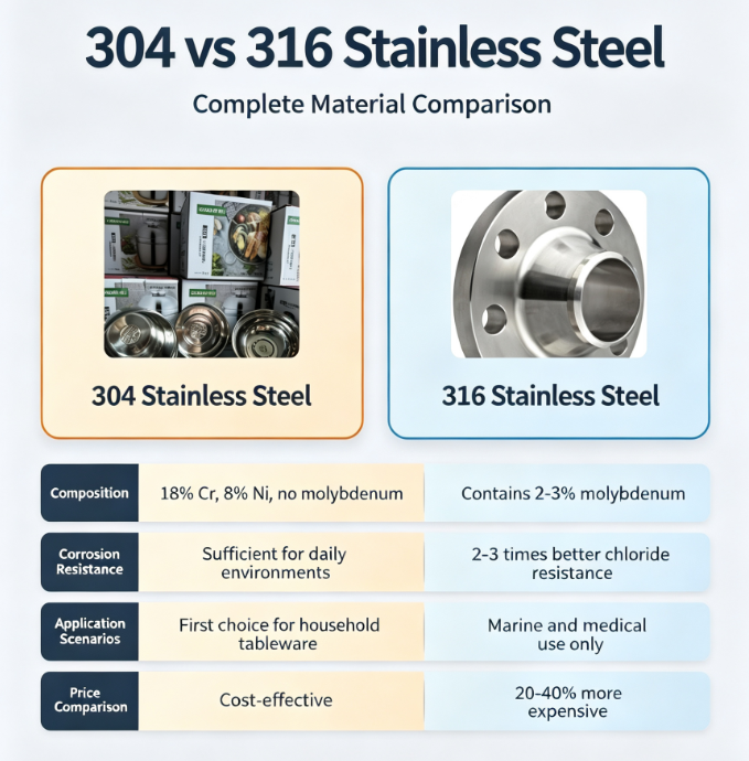
304 vs 316 stainless steel comparison — corrosion resistance and application differences

Engineering Parameters — Full Specification Table

Parameter Specification Process Note
Forming Tolerance ±0.05 mm (critical); ±0.1 mm (general) Die-controlled — verified by first-piece inspection
Bend Angle Accuracy ±0.5° on standard U-bends Springback compensated in die design per material grade
Material Thickness 0.5 – 6.0 mm Thicker gauges require higher tonnage press
Minimum Bend Radius 1.0× material thickness (SS) Below 1×T increases cracking risk on austenitic grades
Hole Position Accuracy ±0.1 mm from nominal Pierced in die station — not drilled post-form
Press Capacity 30T – 200T Mechanical for speed; hydraulic for deep-draw
Surface Roughness Ra 0.8 – 6.3 µm (as-stamped) Post-treatment: Ra 0.2 achievable with polishing
Salt Spray Resistance 316: 500+ hrs; 304: 200+ hrs (passivated) Test per ASTM B117 standard where required
Drawing Input Format CAD / STEP / PDF / DWG / IGES 3D preferred for die programming; 2D for reference

Quality Control System

Stamping quality depends on three variables: die accuracy, material consistency, and press setup. We control all three — and verify the result through measurement, not assumption.
Incoming Material
Thickness verification, hardness check, and composition certification reviewed against order specification before release to production.
First-Piece Inspection
Every new die setup produces a first article that is fully dimensionally verified before the batch is released. Bend angles, hole positions, and flange dimensions checked against drawing.
In-Process Sampling
Periodic dimensional checks at defined intervals during the run. Surface condition and burr height monitored to detect die wear before it accumulates beyond tolerance.
Salt Spray Testing
ASTM B117 corrosion resistance validation for stainless parts destined for outdoor or marine service. Passivation effectiveness confirmed before shipment.
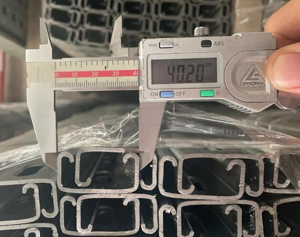
Quality inspection of stamped metal bracket — dimensional measurement with caliper

Surface Treatment — Functional Comparison for Bracket Applications

Surface finish on a bracket is functional, not decorative. It determines corrosion resistance, coating adhesion, and friction behavior at the mounting interface.

Treatment Best Materials Functional Outcome Typical Use
Passivation Stainless 304/316 Removes free iron — enhances chromium oxide layer Marine, chemical, outdoor
Powder Coating Carbon steel, SS Thick polymer barrier — impact + UV resistant Structural, architectural
Electropolishing SS304/316 Smooth surface Ra 0.2 — reduces bacterial adhesion Food-grade, medical
Zinc Plating Carbon steel Sacrificial corrosion barrier — cost-effective Indoor, automotive
Sandblasting All metals Uniform matte texture — pre-treatment for coating Pre-coating prep
Mechanical Polishing SS, brass Mirror surface — low friction, aesthetic Decorative, low-friction
Surface treated stainless steel brackets — passivated, polished, and coated variants

Application Scenarios — Where U-Shaped Stamped Brackets Serve

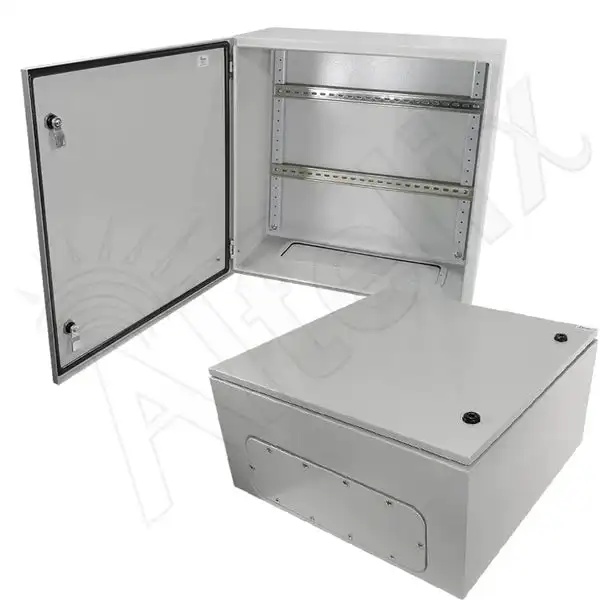
Electrical cabinet mounting bracket — stainless steel U-shaped fixing in enclosure

Electrical Cabinet Mounting

DIN rail and component mounting inside enclosures — 304 grade provides moisture resistance in humid installation environments.
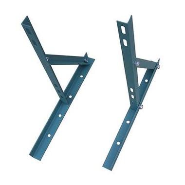
HVAC mounting bracket — structural fixing for climate control equipmentHVAC Structural Fixing

Support brackets for ductwork, condenser mounts, and fan housings — vibration-resilient U-form absorbs dynamic loads without fatigue cracking.

Machinery frame assembly bracket — metal support for industrial equipment

Machinery Frame Assembly

Alignment and joining elements in equipment frames — stamped consistency ensures interchangeability across assembly positions.
Automation equipment bracket — precision mounting for industrial control systems

Automation Equipment

Sensor mounts, actuator brackets, and guide rail clips — tight positional tolerance ensures repeatable alignment in automated lines.

Customization Scope — What We Can Modify

Every bracket we produce starts from your specification. We do not sell from a fixed catalog — the geometry, material, and finish are configured per order. Engineering drawings or physical samples are both accepted as input.
Geometry
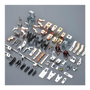
U-shape, L-shape, Z-shape, complex multi-bend profiles — defined by your drawing. Bend radius and flange length adjustable per structural requirement.
Thickness
0.5 – 6.0 mm range. Load-bearing brackets typically 1.5–3.0 mm; lightweight clips at 0.5–1.0 mm. Thickness determines press tonnage requirement.
Hole Pattern
Mounting holes, cable routing slots, fastener clearance — all pierced in the die station. No secondary drilling operations required.
Surface Treatment
Selected per service environment — passivation for corrosion, powder coating for weather, electropolishing for hygiene. We advise, you specify.
Material Grade
SS201 through 316, copper, carbon steel — grade selected by corrosion requirement and formability constraint. Not by price alone.
Input Format
Engineering drawings (CAD/STEP/PDF) or physical samples accepted. We reverse-engineer from sample to production drawing if no CAD exists.
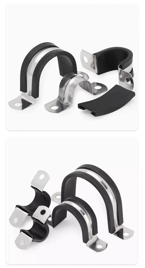
Custom OEM stainless steel U-shaped brackets — various configurations and dimensions

Xiamen Goldcattle stamping production facility — press equipment and quality workshop

Why Xiamen Goldcattle for Stamped Bracket Production

Xiamen Goldcattle Plastic & Metal Products Co., Ltd. operates a vertically integrated facility in Xiamen, China — combining laser cutting, stamping, bending, surface treatment, and dimensional inspection under one ISO 9001 quality system. Your bracket moves from blank stock to verified finished component without leaving our building, eliminating the alignment gaps that occur when blanking, forming, and finishing are distributed across separate suppliers.

24 Years Production Experience
Stamping, bending, and sheet metal fabrication since 2001 — process knowledge embedded in die design, not learned on your order.
In-House Die Design
Tooling designed, fabricated, and maintained under our engineering control — die modifications without external vendor delays.
Integrated Process Chain
Laser blank → stamp → bend → deburr → treat → inspect — one facility, one quality system, one delivery schedule.
Export to North America & Europe
Documentation, packaging, and logistics aligned with international delivery standards. Material certs and inspection reports provided per shipment.

Frequently Asked Questions — Purchasing Decision Reference

What is your stamping tolerance capability?

±0.05 mm on critical formed dimensions, ±0.1 mm on general features. Bend angles held to ±0.5°. Verified through first-piece and periodic in-process measurement.

Can you produce progressive die parts?

Yes. We design and build progressive dies in-house for volumes above 5,000 pcs. Multi-station dies handle blanking, forming, and piercing in one stroke sequence.

What is the MOQ for custom brackets?

100 pieces minimum for custom die orders. Prototype samples (10–50 pcs) available before committing to volume. No MOQ for standard re-order programs.

Can I prototype before mass production?

Yes. Prototype samples produced using laser cutting + CNC bending — no die investment required. When geometry is validated, we design the production die and transition to stamping for volume.

What surface treatment is best for outdoor brackets?

316 stainless with passivation for marine/coastal exposure. 304 with passivation for general outdoor. Carbon steel with powder coating for structural applications where corrosion grade is less critical than impact resistance.

Do you provide material certification?

Yes. Mill certificates, composition analysis, and thickness verification documents included with every order. Full traceability from raw material to finished bracket.

How long does a typical order take?

Prototype (no die): 7–10 days. Custom die + first production run: 15–20 days including die fabrication. Re-orders on existing die: 7–12 days. Surface treatment adds 2–5 days.

What drawing formats do you accept?

CAD, STEP, IGES, DWG, PDF. 3D files preferred for die programming. 2D drawings accepted for reference. Physical samples also accepted — we reverse-engineer to production drawing.

Submit Your Drawing for a Feasibility Review and Quote

Upload your CAD file or send a physical sample — our engineering team evaluates formability, material selection, and die strategy before quoting. No commitment required for prototype samples.


Related Manufacturing Services

Clips, contacts, and formed components — progressive and single-operation die production for high-volume consistency.

Precision blanking and CNC bending for prototype and low-volume runs — no die investment required for initial validation.