I. Concept of the CNC Drilling Process
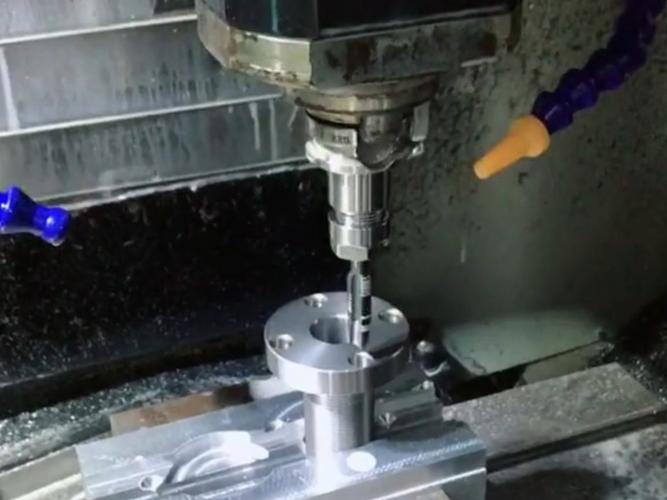
- Main movement: The rotational movement of the drill bit around its axis (cutting movement).
- Secondary movement: The linear movement of the drill bit along the axis direction towards the workpiece (feeding movement).
Commonly used drilling tools include twist drills, center drills, deep – hole drills, etc. Among them, the twist drill is the most commonly used, and its diameter specifications are related to solving processing problems – the classification and comparison of hole – making.
II. Types of CNC Drilling Processes
- Ordinary drilling (twist – drill drilling)
- Deep – hole drilling process
- Reaming process
- Boring process
- Countersinking process
- Peck drilling (intermittent drilling)
- High – speed drilling
- Laser drilling process: Precise carving with laser, achieving minute precision.
- Electrical – discharge drilling process: Shaping with fine details through discharge etching.
- Electrochemical drilling process: Fine processing via electrochemical action.
III. Characteristics of CNC Drilling
The drill bit usually has two main cutting edges. During processing, the drill bit cuts while rotating. The rake angle of the drill bit increases from the center axis to the outer edge. The closer to the outer – circle part, the higher the cutting speed of the drill bit, and the cutting speed decreases towards the center, with the cutting speed at the rotation center of the drill bit being zero. The chisel edge of the drill bit is located near the rotation center axis. The chisel edge has a large negative rake angle, no chip – holding space, and a low cutting speed, thus generating a relatively large axial resistance. If the chisel – edge is ground into type A or type C as per DIN1414, with the cutting edge near the center axis having a positive rake angle, the cutting resistance can be reduced, and the cutting performance can be significantly improved.
Based on differences in workpiece shape, material, structure, and function, drill bits can be classified into many types, such as high – speed steel drill bits (twist drills, gang drills, flat drills), solid carbide drill bits, indexable shallow – hole drills, deep – hole drills, core drills, and replaceable – tip drill bits.
IV. Factors Affecting the Precision of the Machined Hole during Drilling
- The clamping accuracy of the drill bit and cutting conditions, such as the tool holder, cutting speed, feed rate, and cutting fluid.
- The size and shape of the drill bit, such as the drill – bit length, edge shape, and drill – core shape.
- The shape of the workpiece, such as the shape of the hole – side surface, the hole – entrance shape, thickness, and clamping state.
V. Methods to Improve CNC Drilling Precision
- Sharpening the Drill Bit Well Is the Starting Point
Before drilling, the appropriate drill bit should be selected for sharpening. Besides ensuring that the tip angle, clearance angle, and chisel – edge angle are accurate, and that the two main cutting edges are of equal length, symmetric about the drill – bit center line, and the two main flank faces are smooth, for better centering and to reduce the roughness of the hole wall, the chisel edge and the main cutting edge should be properly ground (it is advisable to rough – grind on a grinding wheel first and then finish – grind on an oilstone).
- Accurate Marking Is the Foundation
Mark accurately with a height gauge. First and foremost, ensure the accuracy of the dimensions. When marking, make the angle between the scriber and the workpiece marking plane form an angle of 40 – 60 degrees (along the marking direction), so that the marked lines are clear and uniform. Pay attention to the selection of the marking reference surface. The reference surface should be accurately processed, ensuring its flatness and perpendicularity to adjacent surfaces. After marking the cross – lines of the hole position, to facilitate alignment during drilling, use a center punch to make a center point on the cross – lines (the punch mark should be small and in the correct position).
- Correct Clamping Is Crucial
Ordinarily, for holes with a diameter less than 6mm, if the accuracy requirement is not high, the workpiece can be clamped with pliers for drilling. For holes with a diameter of 6 – 10mm, if the workpiece is regular and flat, it can be clamped with a vise, but the workpiece surface should be perpendicular to the drill – press spindle. When drilling holes with a larger diameter, the vise must be fixed with bolts and pressure plates. For larger workpieces with a drilling diameter of over 10mm, use the method of clamping with pressure plates for drilling.
- Accurate Alignment Is Key
After the workpiece is clamped, don’t rush to start drilling. First, perform alignment. There are static alignment and dynamic alignment. Static alignment means aligning before starting the drill press, aligning the center line of the drill – press spindle with the intersection of the workpiece cross – lines. This method is safe, convenient, and easy for beginners to master. However, since it doesn’t consider uncertain factors such as the run – out of the drill – press spindle, the drilling accuracy is relatively low. Dynamic alignment is carried out after starting the drill press. When aligning, some uncertain factors are taken into account, resulting in relatively higher accuracy.
- Careful Inspection Is Indispensable
Inspection can accurately and promptly detect the precision of the hole, enabling the adoption of necessary compensatory measures. For holes with higher drilling precision, we generally adopt a processing sequence of drilling, reaming, and boring. After drilling a small hole in the first step, use a caliper to measure the offset of the center of the bottom hole from the reference surface. Calculate the position of the bottom hole relative to the ideal center based on the actual measurement. If the offset is no more than 0.10mm, when reaming, appropriately increase the tip angle of the drill bit, weaken the self – centering effect, and gently push the workpiece in the direction of correction, gradually increasing the diameter of the drill tip for compensation. If the offset is more than 0.10mm, use a set of round files to trim the two side walls of the bottom hole. The trimmed part should smoothly transition with the bottom – hole arc.

