Answer:
The main steps of turning include: Firstly, clamp the workpiece and the tool to ensure accurate positioning and firm clamping. Then, adjust the lathe parameters such as rotational speed and feed rate according to the workpiece material and processing requirements. Next, perform tool setting to determine the starting position of the tool. After that, start the lathe for cutting and monitor the processing status during the process. Finally, measure the processed dimensions. If they do not meet the standard, make corrections until the requirements are met.
Professional Extension
I. Clamping the Workpiece and the Tool: Building a Solid Foundation for Processing
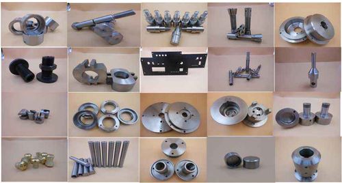
Workpiece clamping is the first step in turning, directly affecting processing accuracy and safety. For shaft – type parts, a three – jaw self – centering chuck or a four – jaw independent chuck is commonly used for clamping. The three – jaw chuck has a strong self – centering ability and is suitable for clamping symmetrical workpieces such as cylinders and regular hexagons. The four – jaw chuck requires manual adjustment of the chuck jaw positions and can clamp eccentric or irregularly shaped workpieces. When clamping, a dial indicator should be used to calibrate the radial run – out of the workpiece to ensure that the error is within the allowable range, preventing uneven cutting force and increased vibration caused by workpiece eccentricity. Tool clamping is equally crucial. When clamping an external turning tool, the tool shank should be perpendicular to the centerline of the lathe, and the tip of the tool should be at the same height as the rotation center of the workpiece. Being too high or too low will change the actual working angle of the tool, affecting cutting performance and processing quality. For internal boring tools, due to their long and slender shanks, the extended length should be shortened as much as possible during clamping to enhance rigidity and reduce vibration.
II. Parameter Adjustment: Precise Setting to Meet Processing Requirements
Adjusting lathe parameters needs to comprehensively consider factors such as workpiece material, tool material, and machining allowance. For high – hardness alloy steel, to reduce tool wear, a lower cutting speed should be selected, generally around 50 – 80m/min. When processing aluminum alloys, the cutting speed can be appropriately increased to 200 – 300m/min. The selection of feed rate is related to processing efficiency and surface quality. During rough machining, a larger feed rate can be used to improve efficiency, such as 0.3 – 0.8mm/r. During finish machining, to ensure surface roughness, the feed rate needs to be controlled within 0.05 – 0.2mm/r. The determination of cutting depth is based on the machining allowance. During rough machining, most of the allowance can be removed, and the cutting depth can reach 3 – 5mm. During finish machining, a 0.5 – 1mm allowance is left for fine cutting. In addition, the spindle speed gear position of the lathe and the position of the feed box handle also need to be adjusted according to the processing requirements to ensure that the parameter settings meet the technological requirements.
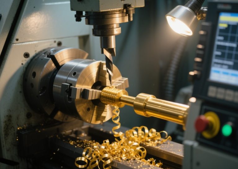
III. Tool Setting Operation: Precise Calibration of the Processing Starting Point
Tool setting is a key step in determining the relative position between the tool and the workpiece. In CNC lathes, the trial – cut tool – setting method is often used. First, manually operate the tool to perform a trial – cut on the outer diameter of the workpiece, measure the diameter size after the trial – cut, and input the data into the machine tool control system. The system calculates the offset of the tool in the X – axis direction based on this. Similarly, perform a trial – cut on the end face of the workpiece to determine the position in the Z – axis direction. When setting the tool on an ordinary lathe, the chuck needs to be rotated manually to bring the tool tip close to the workpiece. The tool position is adjusted based on experience and observation, and tools such as a scriber are used to assist in calibrating the tool height. The accuracy of tool setting directly affects the dimensional accuracy of the workpiece. If the tool – setting error is large, the processed parts may have out – of – tolerance dimensions. Therefore, the tool – setting process needs to be rigorous and meticulous, with multiple measurements and calibrations.
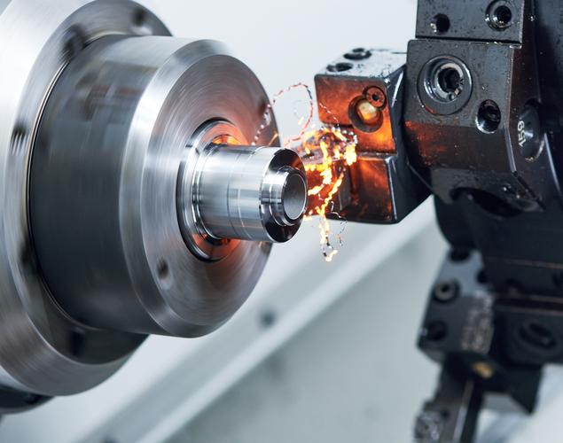
IV. Cutting Processing and Process Monitoring: Quality Control in Dynamic Processing
After starting the lathe for cutting, the operator needs to closely monitor the processing status. During the cutting process, the rationality of cutting parameters can be judged by observing the chip shape. Normal ribbon – shaped chips indicate stable cutting. If there are fragmented chips or abnormal curling, the cutting parameters may need to be adjusted. At the same time, listen to the cutting sound. If a sharp and harsh sound or abnormal vibration sound occurs, it may be due to tool wear, loose workpiece clamping, etc., and the machine should be stopped immediately for inspection. When processing special parts such as deep holes or slender shafts, more intensive monitoring is required to prevent problems such as tool breakage and workpiece deformation. In addition, cutting fluid should be added in a timely manner during the cutting process. The cutting fluid can not only cool the tool, reduce the cutting temperature, but also play a lubricating role, reducing the friction between the tool and the workpiece, improving the surface quality, and extending the tool life.
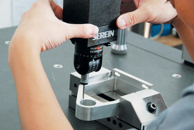
V. Measurement and Correction: The Final Step to Ensure Accuracy
After processing, measuring tools such as calipers, micrometers, and dial indicators are used to measure the dimensions of the workpiece. For shaft – type parts, the outer diameter and cylindricity are mainly measured. For disk – sleeve – type parts, the inner diameter and co – axiality need to be measured. If the measurement results do not meet the design requirements, the cause of the error needs to be analyzed. Determine whether it is due to clamping problems, improper parameter settings, or tool wear, and then make targeted corrections. It may be necessary to readjust the parameters for additional processing or replace the tool for re – cutting. In high – precision machining, multi – dimensional geometric tolerance inspections such as circular run – out and perpendicularity also need to be carried out. Through repeated measurements and corrections, the workpiece is finally ensured to meet the design standards.