Precision CNC · ISO 9001
FROM DESIGN TO REALITY
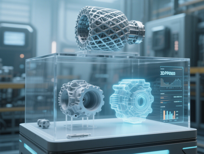
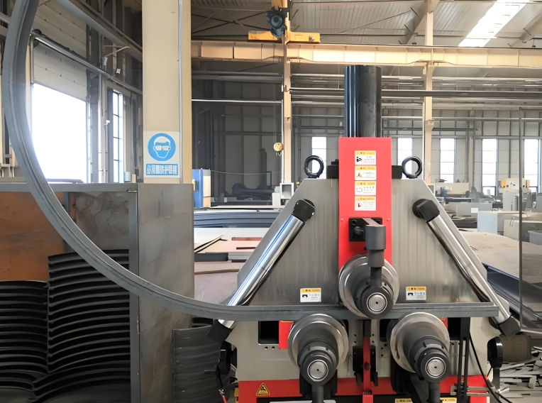
Aluminum prototype machining is the rapid manufacturing of product prototype parts using aluminum alloys (6061, 7075, 5052) via CNC milling, turning, or five-axis machining. Its core transforms 3D models into machine instructions, removing material to form prototypes with high precision and specific properties — essential for aerospace, automotive, and electronics validation.
Machined parts achieve tolerances down to ±0.05mm and can be anodized or plated, enabling functional testing, assembly verification, and appearance review in as fast as 3–5 days.
🔩
density
tensile (7075)
thermal cond.
Figure 1: key physical properties of aluminum alloys for prototyping.
Advanced CNC Machining Equipment & Process
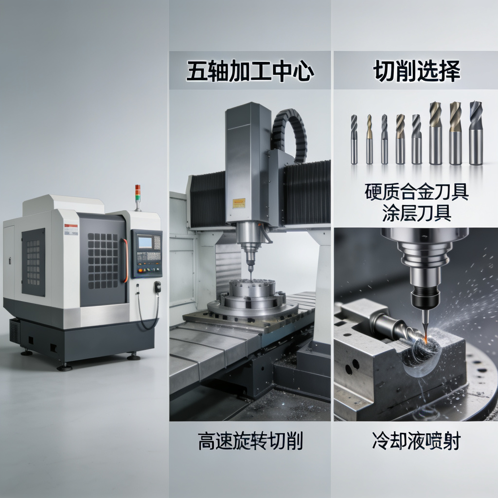
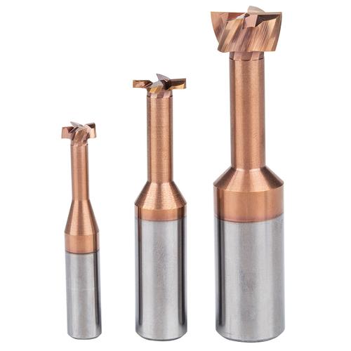
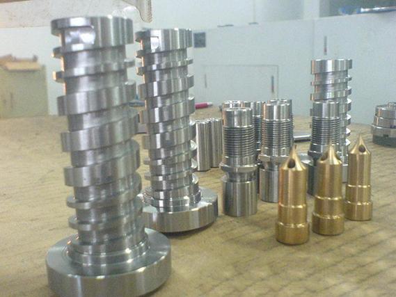
Figure 2: Five-axis CNC machining center and key process stages for aluminum prototype manufacturing.
Machining Technology Overview
🔧 Five-Axis Machining Advantages
- Single setup machining of complex geometries
- Eliminates secondary operations and alignment errors
- Improves surface finish on complex surfaces
- Reduces production time by 40-60%
I. Technical Principles & Machining Characteristics
1. Technical Advantages
- ⚡Physical: density 2.7g/cm³ (1/3 steel), 7075-T6 tensile 310–570MPa – lightweight & high strength.
- 🔥Thermal: conductivity 205W/m·K, aids heat dissipation; anti-adhesive tooling strategies required.
- 🎨Surface: anodizing forms 0.5–25μm oxide film, improves wear & corrosion resistance.
2. CNC Technology Key Points
Tool selection: carbide (YG6) or PCD, sharp edges to avoid burrs.
✪ Turning 7075: linear speed 150–250 m/min to control work hardening.
Thin-walled strategy: multi-layer cutting, e.g., 0.5mm wall in 5 layers (0.2mm allowance).
Aluminum Alloy Materials & Properties
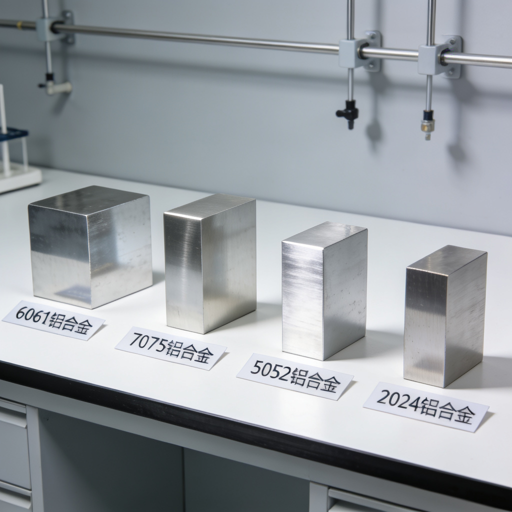
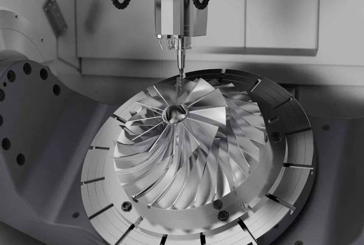
Figure 3: Comprehensive display of aluminum alloy samples for prototype machining.
Material Selection Guide
🔬 6061-T6 Aluminum Alloy
– Tensile strength: 310 MPa
– Elongation: 12%
– Excellent anodizing response
– Applications: Automotive components, UAV frames, general prototypes
💎 7075-T6 Aluminum Alloy
– Tensile strength: 570 MPa
– Hardness: 150 HB
– Ultra-high strength, aerospace grade
– Applications: Aerospace connectors, racing components, high-stress parts
🔧 5052-H32 Aluminum Alloy
– Tensile strength: 210 MPa
– Excellent corrosion resistance
– Good formability
– Applications: Marine components, chemical equipment, medical devices
II. Complete Process Flow Analysis
📦
Preprocessing
Stress relief: 7075 plates annealed 350℃×2h.
Blank allowance: 1–3mm reserved.
Thin-walled eg: 0.5mm wall, 5-layer cutting.
⚙️
Cutting Execution
Rough: end mills φ10–20, emulsion coolant.
Finish: diamond-coated tools, feed ≤0.05mm/r → Ra≤0.4μm mirror finish.
Thread M3: special Al taps + oil.
✨
Post-Processing
Anodizing: sulfuric 5–10μm, hard 25–50μm.
Plating: electroless nickel 5–10μm (salt spray ≥500h).
Deburring: vibratory / electrolytic.
🔹 TiAlN coating reduces friction to 0.3, tool life x3
🔹 Minimum cutting thickness 0.01mm (micro-milling)
III. Technical Terms & Concepts
Goldcattle’s Customization Process
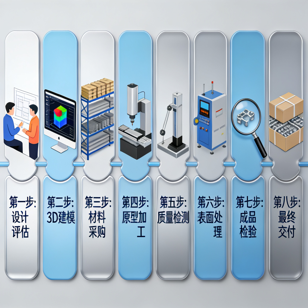
Figure 4: 8-step customization process from initial design to final delivery.
Step-by-Step Customization
- 1
Design Evaluation
Our engineering team reviews your design files to assess feasibility, material suitability, and manufacturing requirements.
- 2
3D Modeling & Programming
Create optimized tool paths using CAM software, considering material properties and machine capabilities.
- 3
Material Preparation
Select and prepare the appropriate aluminum alloy, including stress relief treatment if required.
- 4
CNC Machining
Precision machining using five-axis or three-axis CNC equipment with optimized cutting parameters.
- 5
Quality Inspection
Comprehensive dimensional inspection using CMM, surface roughness testing, and visual inspection.
- 6
Surface Treatment
Anodizing, plating, or other finishing processes as specified in the design requirements.
- 7
Final Verification
Functional testing, assembly verification, and final quality assurance checks.
- 8
Packaging & Delivery
Protective packaging and delivery with complete documentation and quality certificates.
IV. Aluminum Alloys & Part Characteristics
🔧 micro-milling: 0.1mm-wide heat sinks with φ0.5mm tools · depth-diameter ratio >10:1 for aerospace casings.
Quality Control & Inspection Process
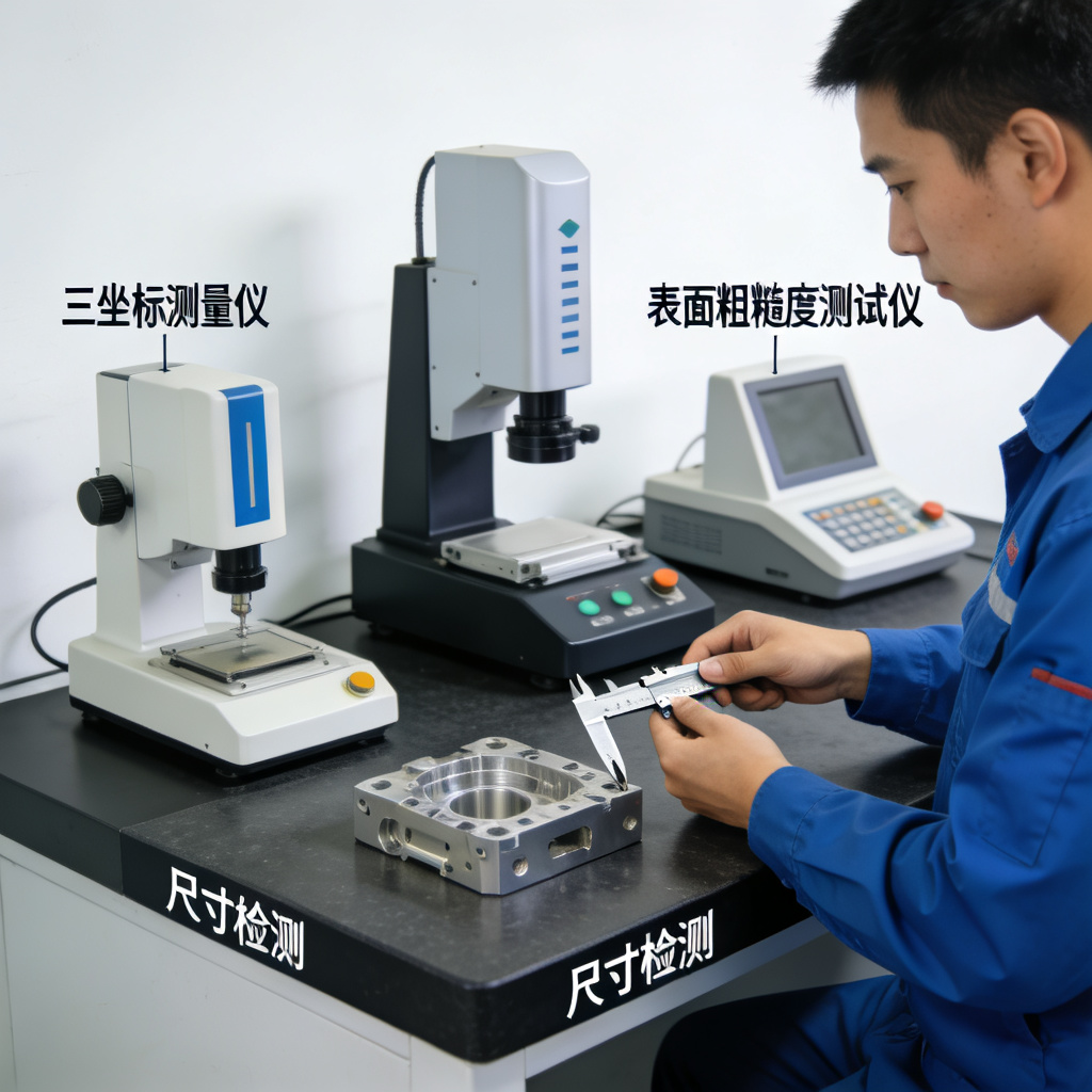
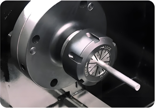
Figure 5: Comprehensive quality inspection using CMM, surface roughness tester, and dimensional measurement tools.
Inspection Capabilities
📐 Dimensional Inspection
– CMM (Coordinate Measuring Machine): ±0.002mm accuracy
– Optical comparator: 0.001mm resolution
– Laser scanning: 3D surface profiling
– Key dimensions verified with calibrated gauges
✨ Surface Quality
– Surface roughness tester: Ra 0.025–100μm range
– Visual inspection under magnification
– Anodize thickness measurement
– Coating adhesion testing
V. Industry Applications & Verification Scenarios
🚗
Automotive
Engine cylinder head prototype: φ45mm valve hole cylindricity ≤0.01mm; battery casing hydrostatic 10MPa, weight -30%.
✈️
Aerospace
Wing connector fatigue test 10^7 cycles, tolerance ±0.03mm; antenna bracket -50℃~+120℃ stability.
📱
Consumer Electronics
Mobile phone middle frame 0.5mm ultra-thin, anodized; cooling module fin spacing 0.8mm, efficiency ≥90%.
🦷
⚙️
From Prototype to Production
Aluminum prototype machining leverages lightweight, high toughness, and machinability to deliver high-precision parts via CNC. At Goldcattle, we combine 6061/7075 expertise, five-axis capabilities, and surface finishing (anodizing, plating) to accelerate your product iteration. Whether aerospace brackets or ultra-thin electronics casings — our ISO 9001 facility ensures ±0.01mm tolerances and rapid turnaround.
Get functional prototypes in as fast as 5 days · Free DFM feedback · Material selection consultation available.