Answer
CNC profile milling refers to a machining process where a numerically controlled (CNC) system guides a profile milling cutter to machine specific cross-sectional contours or 3D cavities directly, by matching the cutter’s edge geometry to the target shape of the workpiece. It is widely used for high-precision machining of complex shapes in molds, aerospace components, etc.
Extended Response
I. Core Principles and Technical Characteristics of CNC Profile Milling
1. Fundamental Logic of Profile Milling
- Cutter-Workpiece Contour Mapping: The cutting edge of the profile mill is shaped to match the desired workpiece contour (e.g., convex, concave, tooth form). The CNC system controls the cutter’s trajectory, enabling the edge to envelop the target shape through precise movement.
- Machining Types:
- 2D profiling: Machining cross-sectional contours (e.g., gear teeth, cam grooves);
- 3D profiling: Machining complex cavities (e.g., injection mold cavities, automotive panel dies).
2. Key Differences from Conventional Milling
| Comparison Dimension | CNC Profile Milling | Conventional Milling |
|---|---|---|
| Cutter Geometry | Specialized profile cutter (custom edge contour) | Universal end mills, ball nose cutters, etc. |
| Machining Logic | Cutter contour directly defines workpiece shape | Contour synthesized via path interpolation |
| Precision Control | Relies on cutter manufacturing precision + CNC trajectory | Relies on interpolation accuracy |
| Efficiency Advantage | One-pass forming of complex contours, reducing processes | Requires multi-step stitching |
II. Classification and Application Scenarios of Profile Milling Cutters
1. Classification by Contour Shape
- Convex profile cutters: Convex edges for machining concave contours (e.g., semi-circular grooves, arc slots).
- Concave profile cutters: Concave edges for machining convex contours (e.g., cam outer profiles, blade edges).
- Tooth profile cutters: Edges designed for specific tooth forms, used for gears, splines (e.g., involute gear cutters).
2. Classification by Machining Dimension
- 2D profile cutters: Straight or simple curved edges for planar contour machining (e.g., door/window profile dies).
- 3D profile cutters: Complex curved edges (e.g., ball nose profile cutters) for 3D cavity machining (e.g., smartphone case molds).
3. Typical Application Scenarios
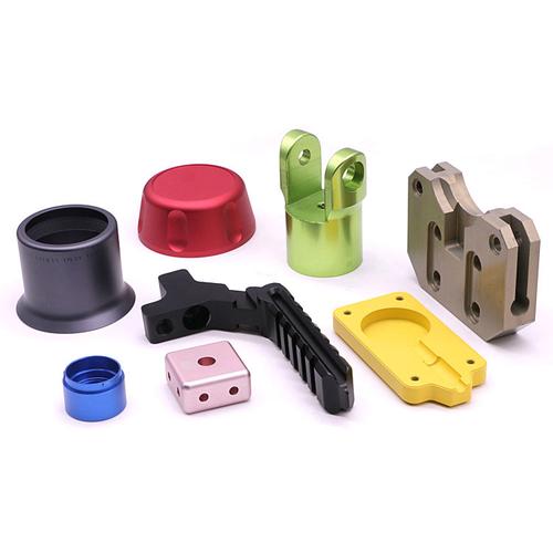
- Mold manufacturing: Mold cavities for injection molding, parting surfaces for die casting, where profile milling directly machines product contours, reducing EDM processes.
- Aerospace: Complex surfaces of engine combustion chambers, root contours of helicopter rotors, formed in one pass via 5-axis profile milling.
- Automotive components: Gear grooves in transmissions, special-shaped holes in engine blocks, improving machining efficiency with profile cutters.
III. Key Technical Elements of CNC Profile Milling
1. Profile Cutter Design and Manufacturing
- Material Selection:
- High-speed steel (HSS): For medium-low speeds (≤100m/min), suitable for cast iron, aluminum alloys;
- Tungsten carbide (WC): For high speeds (100-300m/min), suitable for steel, titanium alloys;
- PCD/CBN: For super-hard materials (e.g., hardened steel HRC60+), cutting speeds up to 500m/min+.
- Cutter Structure:
- Integral profile cutters: High precision, suitable for small parts (e.g., electronic molds);
- Assembled profile cutters: Replaceable inserts reduce costs after edge wear (e.g., large automotive molds).
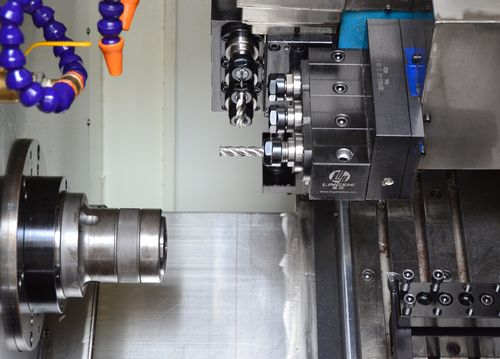
2. CNC Equipment and System Requirements
- Machine Types:
- 3-axis machining centers: Suitable for 2D profiling or simple 3D contours;
- 5-axis machining centers: Enable complex 3D profiling via A/C axis rotation (e.g., impeller blades);
- CNC Systems: Require spline interpolation (e.g., NURBS), tool radius compensation (G41/G42), and length compensation (G43) (e.g., FANUC 0i-MF system).
3. Process Parameter Optimization
- Cutting Speed (V):
- Aluminum alloys: 200-400m/min (carbide tools);
- 45# steel: 80-150m/min (coated carbide);
- Feed Rate (F): Reduce by 20%-30% in profile milling due to larger cutting area (e.g., F=500mm/min in conventional milling vs. F=300-400mm/min in profile milling);
- Axial Depth of Cut (ap): Roughing ap=0.5-2mm, finishing ap≤0.5mm to avoid tool overload.
IV. Process Advantages and Limitations of Profile Milling
1. Core Advantages
- Efficiency Enhancement: One-pass forming of complex contours reduces processes. For example, machining a mold cavity via profile milling reduces 3 processes, shortening the cycle by 40%.
- Stable Precision: Cutter contours directly determine workpiece shape, avoiding cumulative errors from multi-processes, with dimensional tolerances controlled within ±0.02mm.
- Cost Optimization: While profile cutters have higher unit costs, batch production reduces process and fixture costs, lowering comprehensive costs by 15%-30%.
2. Application Limitations
- Strong Tool Specialization: One profile cutter fits only one contour, requiring retooling for product changes, unsuitable for high-mix low-volume production.
- Difficult Cutting Force Control: Large edge contact area prone to vibration, requiring damping tool holders (e.g., SCHUNK TTS) and optimized parameters.
- Complex Surface Constraints: 3D profile milling is limited by cutter geometry, unable to machine undercuts or deep cavities (requires EDM or 5-axis linkage).
V. Comparative Analysis with Other Machining Methods
| Machining Method | CNC Profile Milling | Electrical Discharge Machining (EDM) | 3D Printing (Additive Manufacturing) |
|---|---|---|---|
| Principle | Material removal via cutting | Material removal via electrical erosion | Material accumulation layer by layer |
| Precision | ±0.02-0.1mm | ±0.01-0.05mm | ±0.05-0.2mm |
| Surface Roughness | Ra1.6-3.2μm | Ra0.8-1.6μm | Ra6.3-12.5μm |
| Efficiency | Medium-high (depends on cutter) | Low (low material removal rate) | Medium (depends on layer thickness) |
| Cost | High tooling cost, low batch cost | High electrode cost, suitable for single parts | High material cost, low cost for low volumes |
| Suitable Scenarios | Batch production of complex contours, hard materials | Hard/brittle materials, complex internal cavities | Customization, hollow structures |
VI. Common Process Issues and Solutions
1. Abnormal Tool Wear
- Cause: Excessive cutting speed (e.g., V>100m/min for titanium alloys), insufficient cooling.
- Solution: Reduce speed to 50-80m/min, apply high-pressure cooling (≥5MPa) or MQL (minimum quantity lubrication).
2. Contour Precision Deviation
- Cause: Tool wear, CNC interpolation errors, workpiece vibration.
- Solution: Regularly inspect tool wear (replace when wear land width>0.3mm), enable CNC look-ahead control, add workpiece supports.
3. Surface Waviness
- Cause: Cutting vibration, excessive feed rate.
- Solution: Use damped tool holders, reduce feed to 0.1-0.2mm/tooth, optimize tool path (e.g., helical ramping instead of vertical plunge).
VII. Technological Development Trends
- High-Speed Profile Milling (HSC): Spindle speeds ≥10,000rpm with 5-axis linkage, improving efficiency by 50% and reducing surface roughness by 50% (e.g., DMG HSC 75 linear).
- Intelligent Process Control: Real-time monitoring of cutting force and temperature via sensors, with AI algorithms auto-adjusting parameters (e.g., FANUC’s AI spindle load control).
- Hybrid Profiling Technology: Integration of profile milling with laser texturing for one-pass contour machining and surface texturing (e.g., automotive interior molds).
- Green Profiling Processes: Promotion of dry cutting (e.g., ceramic tools for cast iron), cryogenic cutting (-100℃ cold air cooling) to reduce coolant usage.
VIII. Conclusion
CNC profile milling balances efficiency and precision in complex contour machining through direct “cutter contour-workpiece shape” mapping, serving as a core process in high-end manufacturing fields like molds and aerospace. Its technological development is trending toward high speed, intelligence, and sustainability, and it will further integrate with additive manufacturing, digital twin, and other technologies to expand the boundaries of complex part manufacturing.