How to Prevent Stainless Steel Warping During CNC Machining
Stainless steel warping can result from residual-stress redistribution, cutting forces, workholding deformation, thermal effects and the low stiffness of thin sections. Preventing it starts with identifying the dominant mechanism, then controlling material removal, tool engagement, fixture support and temperature. Final flatness and dimensional stability should be verified after the part is released from its fixture.
This guide is a working reference. Use the in-page anchors to move between diagnosis, prevention methods and inspection — or print / save-as-PDF the checklist at the end. Goldcattle does not host downloadable files on this site.
01 · What Causes Stainless Steel to Warp During CNC Machining?
Three mechanisms produce most distortion in stainless steel machining: elastic deflection under cutting or clamping load, residual-stress redistribution as material is removed, and thermal deformation from temperature change. They are often confused — and each one calls for a different fix, so the first step is identifying which mechanism dominates.
Elastic deflection
The part moves under cutting force or clamping load while it is being machined. When the load is removed, the part may partially recover — leaving it out of shape even though every cut was "on size".
Residual-stress redistribution
Stresses locked into the blank during rolling, forging or welding are held in balance until material is removed or the section changes. The balance shifts and the part bends or twists — often only after it is released.
Thermal deformation
Temperature gradients between the cutting zone and the rest of the part cause uneven expansion. Austenitic stainless steels conduct heat less readily than carbon steel, so more of the generated heat stays concentrated at the cutting zone.
Root-cause diagnosis table
Match the symptom you observe to the likely mechanism before choosing a control method.
| Typical symptom | Possible cause | How to check |
|---|---|---|
| Part bends after the fixture is released | Residual-stress release, or elastic deformation built up during clamping | Compare measurements taken clamped and in the free state |
| Local sag or springback on a thin wall | Cutting-force deflection where wall stiffness is low | Check wall thickness, tool engagement direction, support position and machining order |
| Overall twist after heavy material removal | Uneven removal redistributing internal stress, possibly compounded by thermal effects | Review blank condition, removal distribution and the rough-to-finish sequence |
| Dimensions drift across a continuous run | Tool wear, changing thermal state, or inconsistent clamping | Compare tool-life data, in-process measurements and batch-to-batch records |
| Dimensions pass but assembly fails | Datum, flatness, parallelism or measurement-state mismatch — not size error | Re-check drawing GD&T, measurement datums and free-state acceptance criteria |
Material removal changes the stress balance a blank was supplied with, and thin structures amplify the resulting geometry change. The actual amount depends on the material, structure and machining conditions — results from other parts or materials cannot be transferred to your project.
02 · How to Reduce Warping During Stainless Steel CNC Machining
Distortion control is organised by machining stage: material and blank assessment, removal balance and sequence, workholding, cutting parameters, and thermal conditions. Each stage carries its own checks — none of them is a single universal setting that fixes every part.
1 · Review the material and blank condition before machining
Confirming the grade is not the same as understanding the blank. The form it arrives in — plate, bar, forging or pre-machined — its supplied condition, and its prior processing history all affect how much stress is locked in and how it will release during machining.
- For heavy removal or thin-wall structures, assess the risk that the blank's internal stress state contributes to distortion.
- Keep the heat-treated condition specified on the drawing consistent with the part's final performance requirements.
- If blank stress is the suspected mechanism, evaluate the route with the material supplier and a qualified heat-treatment partner before machining — not by applying a generic cycle.
Stress relief is not a standard step for every 304 or 316 part. Whether it is needed depends on the grade, material condition, the distortion mechanism at work and the downstream performance requirements.
2 · Balance material removal and machining sequence
Removing a large volume from one region changes the force balance in the remaining structure; removing the same volume in a planned, staged pattern keeps it closer to equilibrium. Roughing and finishing order, and the sequence across faces, should follow the structure's risk profile rather than a fixed recipe.
- Where the structure allows, symmetric or staged removal is worth evaluating so stress releases progressively instead of in one step.
- Re-check the part in its free state after roughing — that reading tells you whether the finishing sequence needs adjustment before final dimensions are cut.
- "Multiple light passes" is a direction, not a rule: austenitic grades work-harden, so the strategy must also prevent the tool from rubbing or dwelling on an already machined surface.
3 · Control workholding force and part support
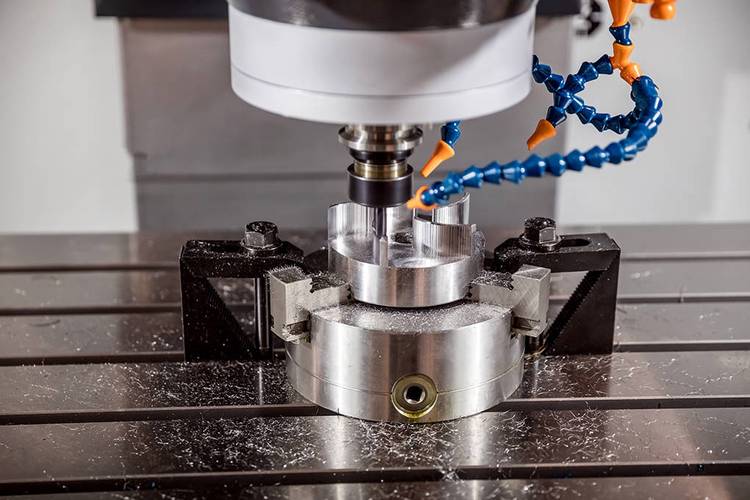
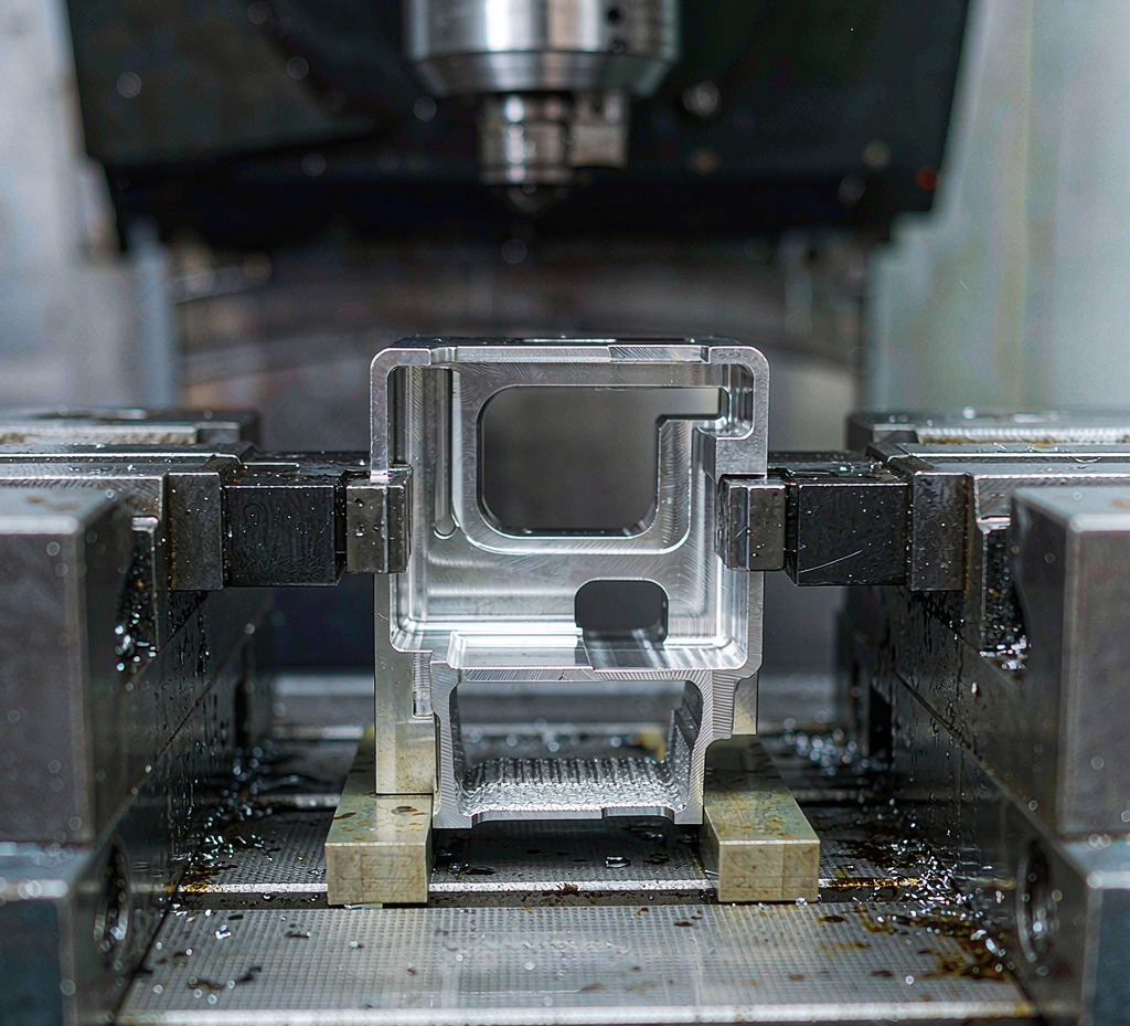
Clamping exists to keep the part from moving — not to force it into a shape it would not otherwise take. The support condition under the cutting zone matters as much as the clamp itself, especially on thin walls.
- Support the part so thin sections and long overhangs are not left unsupported under cutting load; add backing or support blocks where the structure needs them.
- Set clamping force high enough to prevent movement, but low enough that the part is not pre-deformed into the fixture.
- Clamp spacing and layout follow from the part's stiffness, wall thickness, clamping position and machining direction — there is no universal spacing that suits every geometry.
- For distortion-sensitive parts, compare results in the clamped state and after release to learn whether distortion was created during cutting or only revealed once the constraint came off.
Soft jaws, support blocks, vacuum fixtures and staged clamping are all options in the same family: they trade absolute holding force for control over where and how much the part is deformed. Which one fits depends on the part — a vacuum approach that suits a thin plate may be wrong for a pocketed frame.
For multi-material thin-wall distortion control beyond stainless, the thin-wall CNC machining solution page covers stiffness, toolpath and fixturing strategy across materials.
4 · Match cutting parameters to stainless steel and part geometry
No spindle speed, feed rate or depth of cut can be judged apart from the tool that carries it. Parameters are selected together — cutting speed, chip load per tooth, radial and axial engagement — against tool diameter, tooth count, tool material, machine rigidity and the stiffness of the part being cut.
- Austenitic stainless work-hardens: the tool must keep cutting cleanly rather than rubbing or dwelling on an already machined surface.
- Sharp cutting edges, a rigid setup and reliable chip evacuation usually matter more for distortion than any single speed or feed figure.
- Thin-wall parts need the tool-engagement direction and the part's local support evaluated together — the same parameters that are stable on a solid block can deflect a thin wall.
- Parameters are balanced across work hardening, cutting forces, tool life and part stiffness — not optimised for one at the expense of the others.
5 · Maintain consistent cooling and thermal conditions
Cooling serves two purposes: taking heat out of the cutting zone and clearing chips so they do not re-cut or trap more heat. Consistency between operations matters as much as the coolant itself.
- Direct coolant so it actually reaches the cutting zone, and keep chip evacuation reliable — trapped chips hold heat and abrade the surface.
- Let the part reach a stable temperature before measuring; a part measured warm or unevenly cooled can read as distorted when it is not, or read flat when it will move later.
- On dimensionally sensitive programs, record machining and measurement conditions so results from different batches can be compared fairly.
On post-machining correction
Straightening a distorted part with a press or local heat is an engineering disposition, not a repair habit. It needs an agreed allowable deformation range, a defined process, and re-verification of dimensions and surface condition afterwards — and it may not be acceptable for parts with functional or cosmetic requirements.
Unsure which mechanism is driving your distortion? Send the part geometry and the symptom you observe.
03 · How to Verify Flatness and Dimensional Stability After CNC Machining
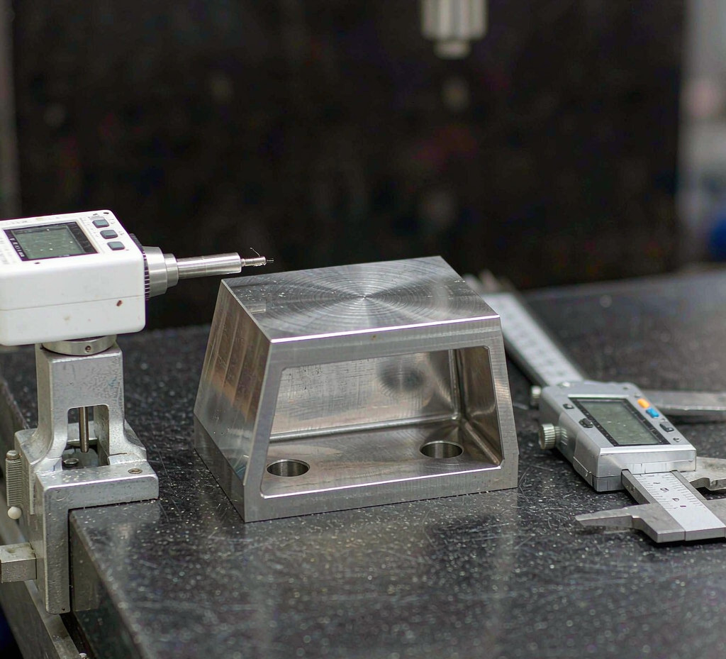
A part is only verified when it is measured in the state it will be used in — released from its fixture, at a stable temperature, against the datums on the drawing. Clamped measurements can pass while the same part fails in assembly.
| Verification item | What to establish |
|---|---|
| Free-state measurement | Measure after the part is released from its fixture, so permanent geometric deviation is separated from clamping restraint |
| Datum & GD&T | Check against the drawing's defined datums — flatness, parallelism and position are drawing requirements, not free-standing numbers |
| Measurement tool selection | Match the method to part size, geometry and tolerance — surface plate and indicator, height gauge, or CMM as appropriate |
| Temperature & measurement state | Let part and instruments stabilise so thermal expansion is not read as distortion, and results stay comparable |
| Process records | Record when and how the part was measured, whether it was clamped or free, the key locations checked, and the drawing revision |
A CMM is not automatically an answer
Measurement accuracy depends on the program, the datum definition, how the part is supported on the machine and the inspection requirement — the machine itself guarantees none of these. The method has to be agreed with the drawing in mind.
Broader supplier-side quality expectations — material verification, FAI, GD&T interpretation and quality documentation — are covered on the CNC supplier quality checks page. Stainless-specific capability, grades and finishing are on the stainless steel CNC machining page.
04 · How to Choose a CNC Supplier for Distortion-Sensitive Stainless Steel Parts
For parts where distortion is the main risk, supplier capability shows up in how they reason about your part — not in a machine list. Five questions separate suppliers who will manage the risk from suppliers who will only accept the tolerance on the drawing.
- Can they explain the distortion risk for your specific geometry? A supplier who only confirms "we can hold ±X" has not yet engaged with the part; one who can point at thin walls, removal balance or stress state is already doing the work.
- Can they describe the workholding, sequence and removal strategy they would use? Fixture layout, rough-to-finish order and staged removal should be explainable decisions, not assumptions.
- Will they verify flatness and critical dimensions after release, under agreed conditions? Ask how the part is supported during measurement, at what temperature, and against which datums.
- Can they provide material certificates and dimensional inspection reports? Material traceability and measured results should be available for the features that matter on your drawing.
- Is there a defined route when a deviation is found? Root-cause analysis, corrective action and re-verification should be a process — not a case-by-case improvisation.
These questions apply to any supplier, including us. The answers you get are a better capability signal than any capability table.
05 · What to Send With a Warping-Sensitive RFQ
A distortion-sensitive inquiry becomes an evaluable project when it carries five things. Send these with your first request so the feasibility review starts from real data instead of assumptions.
| # | Information | What it drives |
|---|---|---|
| 1 | 3D CAD file | Geometry, wall sections and removal assessment |
| 2 | 2D drawing with tolerances and datums | Critical features, flatness requirements and acceptance criteria |
| 3 | Material grade and condition | Work-hardening behaviour, stress state and heat-treatment route |
| 4 | Quantity — initial and annual | Fixture investment, process stability and batch consistency |
| 5 | Critical flatness / dimensional requirements | Measurement method, support strategy and verification plan |
If the drawing is not final, a reference model plus a requirement summary is enough to start. Engineering will confirm what additional data — GD&T, tolerances or interface details — is needed before a firm quote.
06 · Frequently Asked Questions
What causes stainless steel to warp during CNC machining?
Residual-stress redistribution released as material is removed, cutting-force deflection on thin sections, workholding deformation, and thermal effects from temperature gradients. Part stiffness determines how much of that shows up as visible distortion.
Is warping caused by residual stress or cutting heat?
Both are possible and can act together. Compare the part in its fixture and after release: distortion that appears after unclamping points toward stress release, while distortion present during cutting points toward cutting forces or heat. Diagnosis decides the fix.
Does reducing spindle speed prevent stainless steel warping?
Not by itself. Speed, feed, chip load and depth of cut must be selected together against tool diameter, teeth, tool material and part stiffness. For austenitic grades, avoiding tool rubbing and dwell on the work-hardened surface matters more than any fixed RPM.
How can thin-wall stainless steel parts be machined without distortion?
Support the thin section, keep clamping force enough to prevent movement without deforming the part, stage or balance material removal, limit tool engagement on unsupported walls, and verify flatness after release rather than in the fixture.
Should stainless steel be stress-relieved before CNC machining?
It depends. Stress relief is evaluated against the grade, material condition, the distortion mechanism and the part's final performance requirements — it is not a standard step for every 304 or 316 part. Where blank stress is the suspected cause, the route is assessed with the material supplier before machining.
How should flatness be inspected after CNC machining?
Measure in the free state — after the part is released from its fixture — against the drawing datums, using an appropriate method for the part size and tolerance, with the part and instruments at a stable temperature. Record measurement conditions and drawing revision with the results.
What should I send to a CNC supplier for a warping-sensitive part?
3D CAD, a 2D drawing with tolerances and datums, the material grade, quantity, and the critical flatness or dimensional requirements. If the drawing is not final, a reference model and requirement summary is enough to start.
Send your stainless steel CNC drawing for a quote
Send your 3D CAD, 2D drawing with tolerances, material grade and critical flatness requirements. Our engineering team reviews distortion risk, workholding and verification needs, then returns a project-specific proposal.
- Distortion risk reviewed against your geometry
- Free-state verification plan agreed with the drawing
- Material certificates and dimensional reports per project scope

Reviews distortion risk, fixturing strategy and dimensional verification for stainless steel and thin-wall CNC programs. Goldcattle has manufactured custom precision parts since 1998 under an ISO 9001:2015 quality system.