I. What is CNC Machining Tool Chatter?
Tool chatter refers to abnormal vibration between the cutting tool and workpiece during CNC machining, characterized by high-frequency noise (100-5000Hz), uneven machined surfaces (waviness or tool marks), and accelerated tool wear. Unlike tool crash (rigid collision) or overcut (excessive material removal), tool chatter is a dynamic vibration issue—its core hazard lies in reducing machining precision (dimensional error up to 0.1mm) and shortening tool life (by 30%-50% in severe cases), rather than immediate mechanical damage.
II. Tool Chatter Types and Schematic Diagrams (Mark Key Vibration Zones)
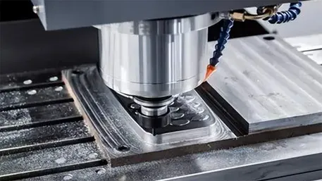
1. Low-Frequency Chatter (50-500Hz)
Scenario: Caused by insufficient clamping rigidity (e.g., workpiece overhang ≥10×thickness), showing obvious workpiece vibration.
Schematic Diagram:
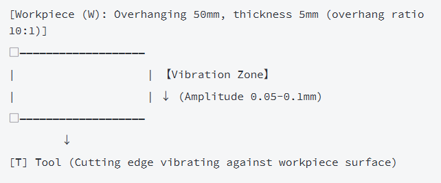
Core Feature: Visible workpiece shaking, machined surface with large waviness (wavelength ≥5mm).
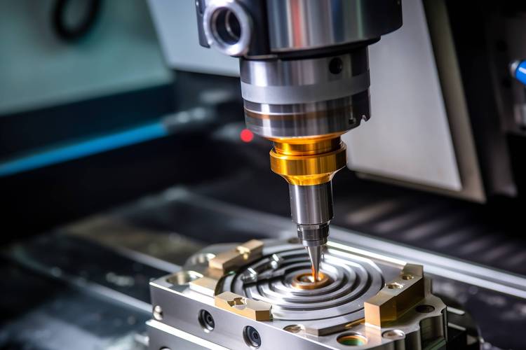
2. High-Frequency Chatter (1000-5000Hz)
Scenario: Caused by low tool rigidity (e.g., long overhang tool: shank length ≥5×diameter), showing sharp “squealing” noise.
Schematic Diagram:
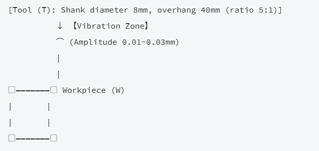
Core Feature: Inaudible workpiece movement, but machined surface with fine tool marks (spacing ≤1mm).
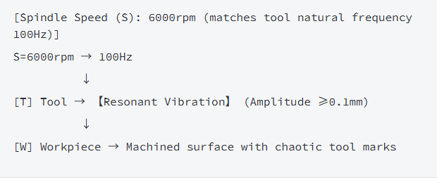
3. Resonant Chatter (Critical Frequency)
Scenario: Machining parameters (spindle speed, feed rate) match the natural frequency of the tool-workpiece system, causing violent vibration.
Schematic Diagram:
III. Four-Step Emergency Handling for Tool Chatter
Step 1: Pause Machining and Assess Impact
- Press the “feed hold” button (not emergency stop) to stop cutting; do not move the tool or workpiece immediately;
- Check two key impacts:
① Surface quality: Whether waviness/tool marks exceed the tolerance (e.g., Ra>1.6μm for general parts);
② Tool status: Whether the cutting edge is chipped (observed with a 10×magnifying glass).
Step 2: Troubleshoot Chatter Causes (with Detection Methods)
Cause 1: Insufficient System Rigidity (40% of Cases)
- Typical Issues: Workpiece overhang too long, fixture clamping loose, tool overhang excessive;
- Detection Method:
-
- Tap the workpiece with a small hammer—prolonged vibration (>2s) indicates low rigidity;
-
- Check tool overhang: For carbide end mills, overhang ratio ≤3:1 (e.g., φ10mm tool overhang ≤30mm);
- Solution:
-
- Add support blocks for overhanging workpieces;
-
- Re-clamp the fixture (torque wrench for uniform force, e.g., 25N·m for M8 bolts);
-
- Replace with shorter tool holders (reduce overhang by 50%).
Cause 2: Improper Cutting Parameters (35% of Cases)
- Typical Issues: Spindle speed too high/low, feed rate too slow, cutting depth excessive;
- Detection Method:
-
- Use the “chatter test”: Increase spindle speed by 10%—if noise reduces, speed was too low;
-
- Check cutting depth: For aluminum alloy, finish milling depth ≤0.2mm (excessive depth increases vibration);
- Solution:
-
- Adjust spindle speed (e.g., reduce by 20% for high-frequency chatter, increase by 15% for low-frequency);
-
- Increase feed rate (e.g., from 800mm/min to 1200mm/min for plastic machining);
-
- Reduce cutting depth by 30%-50% (prioritize multiple passes over deep single passes).
Cause 3: Tool Issues (15% of Cases)
- Typical Issues: Dull cutting edge, tool runout excessive (>0.01mm), incorrect tool geometry;
- Detection Method:
-
- Check tool runout with a dial indicator (mount tool on spindle, rotate and measure);
-
- Test cut on scrap—dull tools cause “scraping” noise and burrs;
- Solution:
-
- Re-grind or replace dull tools;
-
- Use a tool setter to calibrate runout (replace collets if runout exceeds 0.01mm);
-
- Choose tools with larger core diameter (e.g., 0.7×tool diameter) for high-rigidity needs.
Cause 4: Machine Issues (10% of Cases)
- Typical Issues: Spindle bearing wear (runout >0.005mm), loose guideway screws;
- Detection Method:
-
- Measure spindle runout (static runout ≤0.005mm for precision machines);
-
- Check guideway clearance (push the slide with hands—no obvious play);
- Solution:
-
- Replace spindle bearings if runout exceeds limit;
-
- Tighten guideway screws (follow machine manual torque specs).
Step 3: Implement Remedial Measures
|
Chatter Type
|
Priority Measure
|
Expected Effect
|
|
Low-Frequency
|
Add workpiece support + reduce overhang
|
Vibration amplitude ≤0.02mm
|
|
High-Frequency
|
Shorten tool overhang + increase feed rate
|
Noise reduction by 50%
|
|
Resonant
|
Adjust spindle speed (±20%)
|
Resonance elimination
|
Step 4: Test Cut Verification
- Select a scrap piece of the same material;
- Use the adjusted parameters to machine a 50×50mm area;
- Check: ① No abnormal noise/vibration; ② Surface roughness Ra ≤0.8μm; ③ Dimensional error ≤±0.02mm—confirm qualified before formal machining.
IV. Core Prevention Measures for Tool Chatter
1. Design & Clamping Optimization (Pre-Machining)
- Workpiece Design: Avoid overhang ratios >5:1; add reinforcing ribs for thin-walled parts (thickness ≥1mm);
- Fixture Selection: Use vacuum chucks for large flat parts (vacuum degree ≥-0.08MPa); use side clamps for irregular parts (avoid single-point clamping);
- Tool Matching: For deep cavity machining, use modular tool holders (adjust overhang dynamically); choose indexable inserts with positive rake angles (reduce cutting force by 20%).
2. Parameter Setting Standards (Programming)
|
Material
|
Spindle Speed (rpm)
|
Feed Rate (mm/min)
|
Cutting Depth (mm)
|
Tool Overhang Ratio
|
|
Aluminum 6061
|
8000-12000
|
1200-2000
|
0.1-0.3 (Finish)
|
≤3:1
|
|
Stainless Steel 304
|
3000-5000
|
500-1000
|
0.05-0.2 (Finish)
|
≤2.5:1
|
|
ABS Plastic
|
6000-9000
|
1500-2500
|
0.2-0.5 (Finish)
|
≤4:1
|
3. Real-Time Monitoring (Machining)
- Sound Monitoring: Train operators to recognize chatter noise (differentiate from normal cutting “rustling”);
- Vibration Sensors: Install wireless vibration sensors (range 0-1000Hz) on the spindle—set alarm threshold at 0.05mm amplitude;
- Surface Inspection: Use a portable roughness tester to spot-check every 10 workpieces (Ra>1.6μm triggers parameter adjustment).
4. Machine Maintenance (Regular)
|
Maintenance Item
|
Cycle
|
Standard Requirement
|
|
Spindle Runout Check
|
Monthly
|
Static runout ≤0.005mm
|
|
Guideway Lubrication
|
Daily
|
Oil pressure ≥0.3MPa, no leakage
|
|
Tool Collet Cleaning
|
Weekly
|
No wear, runout ≤0.003mm after installation
|
V. Summary
Tool chatter is a “silent killer” of machining quality—its root cause is the imbalance of the “tool-workpiece-machine” rigidity system. The core solution lies in: “optimizing rigidity as the foundation, adjusting parameters as the key, and real-time monitoring as the guarantee”. By following the “detection-remediation-verification” process, 90% of chatter issues can be resolved, and the machining qualification rate can be improved from 80% to over 98%.