CNC milling is a subtractive manufacturing process where computer-controlled milling machines use rotating cutting tools to remove material from a workpiece, shaping it into precise 2D or 3D geometries. It automates tool movements (X, Y, Z axes, and rotational axes in multi-axis systems) via preprogrammed G-code, enabling consistent production of complex parts with tight tolerances across metals, plastics, and composites.
Detailed Analysis of the CNC Milling Process
1. Core Technologies & Equipment
CNC milling relies on advanced hardware and software to achieve precision and versatility:
-
Machine Types:
- 3-axis mills: Move along X, Y, and Z axes, suitable for flat or simple 3D parts (e.g., brackets, panels) with tolerances of ±0.01mm.
- 4-axis mills: Add a rotary A-axis, allowing the workpiece to rotate around the X-axis. Ideal for parts with features on cylindrical surfaces (e.g., gear teeth, slots on a rod).
- 5-axis mills: Integrate A and B axes (rotating around X and Y), enabling simultaneous multi-directional cutting. Used for complex geometries like turbine blades or mold cavities, achieving tolerances as tight as ±0.001mm.
-
Cutting Tools:
- End mills: Cylindrical tools with cutting edges on the end and sides, used for profiling, slotting, and face milling. Carbide end mills (coated with TiAlN) excel in hard materials (steel, titanium), while high-speed steel (HSS) tools suit aluminum or brass.
- Face mills: Large-diameter tools with multiple inserts for flattening large surfaces (e.g., metal plates), achieving Ra <1.6μm finishes.
- Ball-nose mills: Round-tipped tools for 3D contouring (e.g., curved mold surfaces), minimizing scallop height (the step between tool paths) to <0.005mm.
-
Control Systems:
CNC controllers (e.g., Fanuc, Siemens Sinumerik) interpret G-code to regulate spindle speed (1,000–40,000 RPM), feed rate (50–5,000 mm/min), and axis movements. Modern systems include features like adaptive control, which adjusts parameters in real time to reduce vibration or tool wear.
2. Step-by-Step Milling Workflow
The process follows a structured sequence to ensure accuracy and efficiency:
-
Design & Programming:
- Engineers create a 3D CAD model (using SolidWorks or Fusion 360) with specified dimensions (e.g., 100×50×10mm block with 8mm holes).
- CAM software converts the CAD model into toolpaths, optimizing cutting strategies:
- Roughing: Removes 70–80% of material with deep cuts (2–5mm) and high feed rates to save time.
- Finishing: Uses shallow cuts (0.1–0.3mm) and slow feeds to refine surfaces and meet tolerances.
- The CAM outputs G-code, which includes commands like
G01 X50 Y30 F200;(linear movement) andM03 S10000;(spindle start at 10,000 RPM).
-
Workpiece Setup:
- The raw material (e.g., aluminum block, steel sheet) is clamped to the machine table using vises, clamps, or vacuum chucks. For thin-walled parts (≤1mm), vacuum chucks prevent distortion by distributing holding force evenly.
- Work offsets (G54–G59) are set using a probe or edge finder to align the workpiece with the machine’s coordinate system, ensuring the toolpath matches the part’s geometry.
-
Tool Loading & Calibration:
- Cutting tools are loaded into the tool changer, and their lengths/diameters are measured using a tool setter. Offsets are stored in the controller (e.g., Tool 1: 10mm end mill with length offset 50.2mm).
- This calibration ensures the machine “knows” the tool’s position relative to the workpiece, preventing overcuts.
-
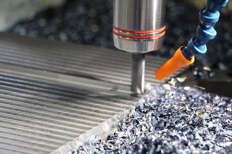
Milling Execution:
- The machine runs the G-code, with the spindle rotating the tool while axes move to cut the workpiece. Coolant is sprayed at the cutting zone to reduce heat and flush chips—critical for preventing tool wear in high-speed machining of titanium.
- For 5-axis parts (e.g., aerospace brackets), the machine adjusts rotational axes mid-cut to maintain optimal tool contact with complex surfaces.
-
Post-Processing & Inspection:
- Deburring removes sharp edges using brushes or abrasive media.
- Dimensional checks with calipers, micrometers, or CMMs verify features like hole position (±0.01mm) or flatness (≤0.002mm/m). Surface finish is measured with a profilometer to ensure Ra values meet specs (e.g., Ra <0.8μm for hydraulic components).
3. Material-Specific Considerations
Different materials require adjusted parameters to optimize results:
-
Metals:
- Aluminum (6061, 7075): Easy to machine with high speeds (15,000–30,000 RPM) and HSS or carbide tools. Uses water-soluble coolant to prevent oxidation. Ideal for lightweight parts (e.g., drone frames) with Ra <1.6μm finishes.
- Steel (304 stainless, 4140): Requires carbide tools with TiAlN coatings to resist wear. Lower speeds (5,000–10,000 RPM) and oil-based coolant reduce heat. Used for structural parts (e.g., engine brackets) needing strength.
- Titanium (Ti-6Al-4V): Low thermal conductivity demands slow speeds (2,000–5,000 RPM) and rigid tool holders to avoid overheating. Cryogenic cooling (liquid nitrogen) enhances tool life for aerospace components.
-
Plastics & Composites:
- ABS, PC: Machined at 3,000–8,000 RPM with HSS tools to avoid melting. Uses compressed air instead of coolant for clean finishes (e.g., electronic housings).
- Carbon Fiber Reinforced Polymers (CFRP): PCD tools with negative rake angles prevent fiber fraying. Low feeds (0.01–0.03 mm/rev) ensure structural integrity in aerospace panels.
4. Typical Products & Industry Applications
CNC milling produces parts across diverse sectors:
- Aerospace: 5-axis mills create turbine blades, wing ribs, and fuel system components from titanium or Inconel, requiring ±0.002mm tolerances and Ra <0.4μm finishes to meet aerodynamic standards.
- Automotive: Milling machines produce engine blocks, gearbox housings, and suspension parts from aluminum or cast iron, balancing precision (±0.05mm) with high-volume efficiency.
- Medical Devices: Titanium implants (knee replacements, dental abutments) are milled to ±0.005mm tolerances, with smooth surfaces (Ra <0.02μm) to prevent tissue irritation.
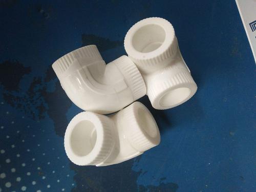
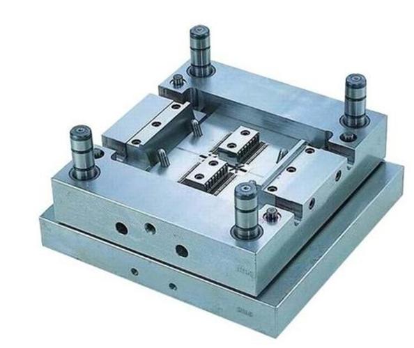
- Tooling & Molds: Mold inserts for injection molding are milled with 5-axis machines to achieve complex cavities (e.g., smartphone case molds) with Ra <0.1μm finishes for glossy plastic parts.
5. Common Challenges & Solutions
- Vibration (Chatter): Causes wavy surfaces. Solved by shortening tool overhang (≤3× diameter), using damping tool holders, or adjusting spindle speed to avoid resonance.
- Tool Wear: Reduces precision over time. Mitigated by using coated carbide tools, monitoring wear with in-process probes, and replacing tools at 80% of their lifespan.
- Surface Defects (Scratches): Caused by loose chips or dull tools. Fixed with high-pressure coolant, sharp tools, and post-machining ultrasonic cleaning.
- Thin-Wall Distortion: Occurs in parts <2mm thick. Prevented by using vacuum chucks, low cutting forces, and machining in multiple light passes instead of deep cuts.
By integrating advanced machinery, material expertise, and precise programming, CNC milling delivers consistent, high-quality parts—making it a cornerstone of modern manufacturing for both prototyping and mass production.