Poor dimensional accuracy in CNC parts can be resolved by calibrating equipment, optimizing processes, controlling material stability, improving fixturing, and enhancing inspection. Key steps include regular machine calibration, using high-precision tools, adjusting cutting parameters to reduce stress, stabilizing material temperature, and implementing strict in-process measurements to catch deviations early.
Detailed Analysis of Resolving Dimensional Accuracy Issues in CNC Machining
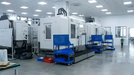
1. Equipment Calibration & Maintenance
The foundation of accuracy lies in the CNC machine’s precision, requiring rigorous calibration and upkeep:
- Axis Positioning Calibration: Use laser interferometers to verify linear and angular positioning accuracy of machine axes (X, Y, Z, and rotational axes for 5-axis machines). For example, checking for backlash (ideally <0.001mm) in ball screws and compensating via the CNC controller’s error map. This reduces cumulative errors in long workpieces (e.g., 1m-long structural parts) by 30–50%.
- Spindle Runout Control: A spindle with excessive runout (>0.002mm) causes uneven cutting forces. Regularly inspect and replace worn bearings, and use dynamic balancing tools to ensure spindle stability at high speeds (10,000–30,000 RPM). This is critical for precision parts like medical implants, where 0.005mm runout can ruin dimensional accuracy.
- Thermal Error Compensation: CNC machines expand/contract with temperature changes (e.g., steel beds expand ~0.012mm/m per °C). Install thermal sensors to monitor ambient and machine temperatures, then use the controller’s compensation software to adjust tool paths. For example, a 5°C rise in a 2m machine can be compensated by offsetting axes by 0.12mm, preventing cumulative errors.
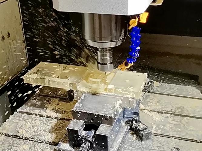
2. Process Optimization & Parameter Tuning
Refining machining processes minimizes errors from cutting forces, tool wear, and workflow inconsistencies:
-
Cutting Parameter Adjustment:
- Reduce Cutting Forces: High feed rates or deep cuts can deform workpieces, especially thin-walled parts (≤1mm thick). For aluminum alloys, use high spindle speeds (15,000–25,000 RPM) and low feed rates (0.05–0.1 mm/rev) to minimize pushing forces. For steel, opt for carbide tools with positive rake angles (5–10°) to shear material rather than crush it, reducing stress-induced distortion.
- Control Chip Evacuation: Poor chip removal (e.g., in deep holes or slots) causes re-cutting, leading to dimension errors. Use high-pressure coolant (70–100 bar) to flush chips, and select tools with large flutes (e.g., 3-flute end mills for aluminum) to improve chip flow.
-
Machining Sequence Optimization:
- Roughing → Semi-Finishing → Finishing: Roughing removes 70–80% of stock quickly but leaves 0.5–1mm of stock to absorb residual stress. Semi-finishing refines shapes to within 0.1–0.2mm of final dimensions, and finishing (with small tools, 3–6mm diameter) achieves tight tolerances (±0.005mm). This sequence prevents stress release from distorting finished surfaces.
- Avoid Over-Machining: For complex parts (e.g., turbine blades with twisted airfoils), use 5-axis continuous machining to maintain consistent tool contact, reducing scallop heights (the step between tool paths) to <0.005mm—far better than stepwise 3-axis machining.
3. Material Stability & Thermal Control
Material properties and temperature fluctuations are major sources of dimensional errors, requiring targeted controls:
-
Material Pre-Treatment:
- Stress Relief Annealing: Metals like steel (4140) or aluminum (7075) often have residual stresses from forging/rolling, which warp parts during machining. Annealing (heating to 300–500°C, then cooling slowly) releases these stresses, reducing post-machining deformation by 60–80%. This is critical for large parts (e.g., 1m-long machine frames).
- Thermal Stabilization: Let materials acclimate to the machining environment (20±2°C) for 24–48 hours. For example, titanium alloys (Ti-6Al-4V) have high thermal conductivity—even a 3°C temperature difference between the material and machine can cause 0.03mm errors in a 100mm part.
-
Temperature Management During Machining:
- Coolant Systems: Use oil-based coolants for high-speed machining of metals (e.g., Inconel) to reduce friction-induced heat. For aluminum, water-soluble coolants (kept at 18–22°C) prevent thermal expansion, which can increase hole diameters by 0.01mm per 5°C rise.
- Ambient Temperature Control: Maintain workshop temperatures at 20±1°C with HVAC systems. This is non-negotiable for precision parts (e.g., optical lens mounts) where 0.001mm accuracy is required.
4. Fixturing & Workpiece Support
Inadequate fixturing causes workpiece movement or deformation, undermining accuracy:
-
Rigid Fixturing Design:
- Use custom jigs or vises with multiple contact points to distribute clamping force. For thin-walled parts (e.g., 0.8mm aluminum brackets), vacuum chucks or magnetic tables provide uniform holding without distortion—reducing dimensional errors by 40% compared to single-point clamps.
- Add support structures (e.g., temporary webs or sacrificial bases) for deep cavities or tall features. For example, a 50mm-deep slot in a brass part can be machined with a support pin inside the slot to prevent wall deflection, then removed in final steps.
-
Clamping Force Calibration:
- Over-clamping distorts parts—use torque wrenches to apply consistent force (e.g., 20–30 Nm for steel, 5–10 Nm for aluminum). For sensitive materials like PEEK plastic, use rubber-tipped clamps to avoid indentations that mimic dimensional errors.
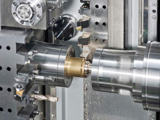
5. Tooling & Tool Management
Tool wear, runout, or mismatched geometry directly cause dimension deviations:
-
High-Precision Tooling:
- Select tools with tight tolerances: carbide end mills with <0.002mm runout, and drills with ground flutes for straightness. Coated tools (TiAlN, AlCrN) last 2–3x longer than uncoated ones, maintaining consistent cutting performance across batches.
- Match tool size to part features: avoid using a 10mm end mill for a 5mm-deep slot, as the long overhang causes vibration (chatter), leading to wavy surfaces and dimension errors.
-
Tool Wear Monitoring:
- Implement in-process probing (e.g., Renishaw OMP40) to measure tool length and diameter after every 50–100 parts. Automatically update tool offsets in the CNC controller to compensate for wear (e.g., a 0.003mm reduction in tool diameter requires a 0.003mm adjustment in cutting depth).
- Replace tools at predefined intervals: for example, high-speed steel drills in brass should be replaced after 500 holes to prevent enlarged diameters.
6. Inspection & Quality Control
Strict measurement protocols catch errors early and prevent recurrence:
-
In-Process Inspection:
- Use CNC-integrated probes to check critical dimensions (e.g., hole position, part length) after roughing and semi-finishing. For example, if a bore is measured 0.01mm undersized, the finishing pass can be adjusted to remove additional material, avoiding scrap.
-
Post-Machining Metrology:
- Coordinate Measuring Machines (CMMs) with ±0.0005mm accuracy verify final dimensions against CAD models. For complex parts (e.g., automotive transmission gears), 3D optical scanners compare the machined surface to the digital design, highlighting deviations as small as 0.002mm.
- Statistical Process Control (SPC): Track key dimensions (e.g., shaft diameter) across 50+ parts using control charts. If measurements drift beyond the tolerance band (e.g., +0.005mm), adjust processes (e.g., tool offsets, cutting speed) before mass defects occur.
7. Industry-Specific Solutions
Different sectors demand tailored approaches to accuracy:
- Aerospace & Defense: Parts like engine nozzles (tolerance ±0.001mm) require daily machine calibration with laser interferometers and 100% CMM inspection. Thermal compensation software adjusts for temperature fluctuations during long runs (e.g., 8-hour machining of a titanium bracket).
- Automotive Mass Production: High-volume parts (e.g., sensor housings) use automated gauging stations with vision systems to check dimensions in <2 seconds per part. SPC ensures 99.9% of parts stay within ±0.01mm, with tool changes triggered automatically when wear is detected.
- Medical Devices: Implants (e.g., knee replacements) need micron-level accuracy. Machining uses ultra-stable 5-axis machines in 恒温 rooms (20±0.5°C), with post-machining inspection via electron microscopy to verify surface and dimensional integrity.
8. Common Scenarios & Fixes
- Thin-Wall Deformation: Use low-feed, high-speed machining (15,000 RPM) with carbide tools to minimize cutting forces. Add temporary supports (e.g., 3D-printed jigs) for walls <1mm thick.
- Thermal Expansion Errors: Machine parts in a climate-controlled room, and let finished parts cool to 20°C before inspection. For large steel parts, this can reduce post-machining length changes by 0.05mm.
- Vibration-Induced Errors: Tighten machine foundations, use vibration-damping pads, and adjust spindle speed to avoid resonance (e.g., 8,000 RPM instead of 10,000 RPM for a 200mm-long part).
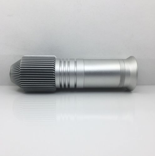
By integrating equipment calibration, process optimization, material control, and rigorous inspection, manufacturers can consistently achieve tight dimensional tolerances, ensuring CNC parts meet performance and assembly requirements across industries.