1. Understanding End Mill Types and Applications
1.1 Square End Mills
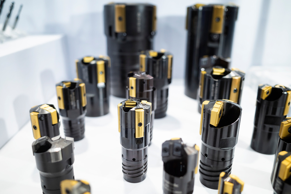
- Cutting Geometry: Flat bottom with 90° corners
- Applications: Face milling, side milling, slotting, shoulder milling
- Material Compatibility: Suitable for most materials
- Advantages: Versatile, cost-effective, good for general purpose machining
- Limitations: Sharp corners prone to chipping, not ideal for 3D contours
- Flat Surface Machining: Creating flat surfaces and shoulders
- Slotting Operations: Cutting slots and grooves
- Shoulder Milling: Machining 90° shoulders
- General Purpose Machining: Ideal for most common milling tasks
1.2 Ball Nose End Mills
- Cutting Geometry: Hemispherical tip with radius equal to half the tool diameter
- Applications: 3D contouring, curved surface machining, mold making
- Material Compatibility: All materials, especially effective for hard materials
- Advantages: Excellent surface finish, can machine at any angle, ideal for complex shapes
- Limitations: Lower material removal rate, reduced rigidity
- 3D Surface Machining: Complex curved surfaces and contours
- Mold and Die Making: Cavity machining and contouring
- Prototyping: Creating complex prototypes
- Finishing Operations: Achieving high-quality surface finishes
1.3 Corner Radius End Mills
- Cutting Geometry: Flat bottom with rounded corners (radius typically 0.2-0.8mm)
- Applications: Roughing and finishing, edge profiling, strengthening part corners
- Material Compatibility: All materials, especially effective for titanium and hard metals
- Advantages: Increased edge strength, reduced chipping, improved surface finish
- Limitations: Slightly higher cost than square end mills
- Strength Critical Parts: Strengthening part corners to reduce stress concentrations
- Titanium Machining: Improved edge life when machining difficult materials
- High Performance Components: Aerospace and automotive critical parts
- Finishing Operations: Achieving better surface finishes than square end mills
1.4 Aluminum-Specific End Mills
- Cutting Geometry: High helix angle (40-45°), polished flutes, sharp cutting edges
- Applications: Aluminum and non-ferrous material machining
- Material Compatibility: Aluminum alloys, copper, brass, plastics
- Advantages: Excellent chip evacuation, reduced built-up edge, high cutting speeds
- Limitations: Not suitable for ferrous materials
- High-Speed Aluminum Machining: Maximizing productivity in aluminum applications
- Aerospace Components: Aircraft parts and structural components
- Automotive Parts: Aluminum castings and components
- Electronic Enclosures: Heat sinks and chassis components
1.5 Roughing End Mills
- Cutting Geometry: Wavy or serrated cutting edges, large chip gullets
- Applications: High-volume material removal, roughing operations
- Material Compatibility: All materials
- Advantages: High material removal rates, reduced cutting forces, improved chip evacuation
- Limitations: Poor surface finish, not suitable for finishing
- Bulk Material Removal: Removing large amounts of material quickly
- High-Volume Production: Maximizing productivity in production environments
- Deep Cavity Machining: Efficient roughing of deep pockets and cavities
- Cost-Effective Machining: Reducing cycle times and improving productivity
2. End Mill Material Selection
2.1 High-Speed Steel (HSS)
- Hardness: 62-65 HRC
- Heat Resistance: Up to 540°C (1000°F)
- Toughness: Excellent resistance to shock and vibration
- Cost: Low to moderate
- Cost-Effective: Lower initial cost compared to carbide
- Toughness: Better resistance to chipping and breakage
- Sharpening: Can be resharpened multiple times
- Versatility: Suitable for a wide range of materials
- Heat Resistance: Limited to lower cutting speeds
- Wear Resistance: Higher wear rates than carbide
- Productivity: Lower material removal rates
- Low-Volume Production: Prototyping and small batch production
- Soft Materials: Aluminum, brass, and plastic machining
- Low-Speed Machines: Older machines with limited spindle speed
- General Purpose: Simple machining tasks with moderate requirements
2.2 Carbide End Mills
- Hardness: 90-93 HRC
- Heat Resistance: Up to 1000°C (1830°F)
- Wear Resistance: Excellent compared to HSS
- Cost: Moderate to high
- High-Speed Machining: Capable of much higher cutting speeds
- Longer Tool Life: Significantly longer than HSS tools
- Better Surface Finish: Improved surface quality
- Higher Productivity: Increased material removal rates
- Brittleness: More prone to chipping and breakage
- Cost: Higher initial investment
- Vibration Sensitivity: Requires more rigid setups
- High-Volume Production: Mass production environments
- High-Speed Machining: Modern CNC machines with high spindle speeds
- Hard Materials: Steel, stainless steel, titanium
- Precision Machining: Tight tolerance applications
2.3 Carbide Grades and Microstructures
- Grain Size: 0.5-1.0 μm
- Properties: High hardness, good wear resistance
- Applications: Precision machining, finishing operations
- Grain Size: 1.0-2.0 μm
- Properties: Balanced hardness and toughness
- Applications: General purpose machining
- Grain Size: 2.0-5.0 μm
- Properties: High toughness, good shock resistance
- Applications: Roughing operations, heavy cutting
2.4 Ceramic End Mills
- Hardness: 95-97 HRC
- Heat Resistance: Up to 1600°C (2910°F)
- Wear Resistance: Excellent
- Cost: High
- Extreme Hardness: Can machine materials up to 65 HRC
- High-Temperature Performance: Maintains hardness at elevated temperatures
- Chemical Inertness: Resistant to chemical reactions with workpiece materials
- Long Tool Life: Excellent wear resistance
- Brittleness: Very high brittleness, prone to catastrophic failure
- Cost: Very expensive
- Setup Requirements: Requires extremely rigid setups
- Hardened Steels: Materials above 45 HRC
- High-Temperature Alloys: Inconel, Hastelloy, Waspaloy
- High-Speed Machining: Very high cutting speeds
- Finishing Operations: Precision finishing of hard materials
2.5 Diamond-Coated End Mills
- Hardness: 98 HRC
- Heat Resistance: Up to 700°C (1290°F)
- Coefficient of Friction: Very low (0.1-0.15)
- Cost: Very high
- Extreme Hardness: Highest hardness of any cutting tool material
- Low Friction: Excellent chip evacuation, reduced built-up edge
- Chemical Inertness: Resistant to most chemicals
- Long Tool Life: Exceptional life in appropriate applications
- Cost: Very expensive
- Ferrous Material Incompatibility: Reacts with iron at high temperatures
- Brittleness: Prone to chipping on impact
- Non-Ferrous Materials: Aluminum, copper, brass
- Composites: Carbon fiber, fiberglass, G10/FR4
- Plastics: Engineering plastics, PEEK, PTFE
- Graphite: Electrodes and carbon components
3. End Mill Coating Technologies
3.1 Coating Fundamentals
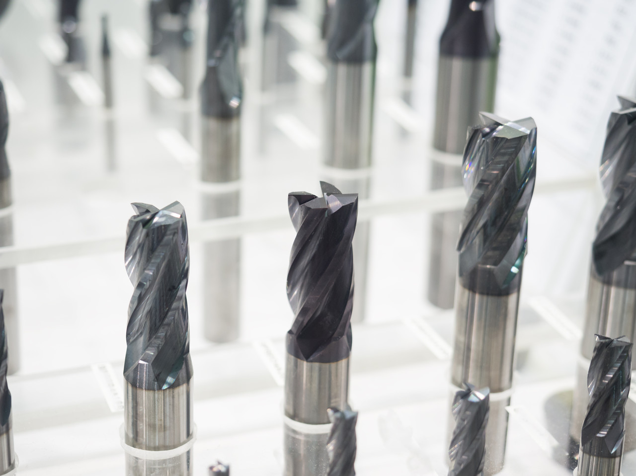
- Increased Wear Resistance: Hard coatings protect the tool substrate
- Reduced Friction: Lower coefficient of friction improves chip flow
- Heat Resistance: Thermal barrier properties protect the tool from high temperatures
- Chemical Protection: Resistant to chemical reactions with workpiece materials
- Improved Surface Finish: Smoother cutting action produces better surface quality
3.2 Common Coating Types
- Color: Gold
- Hardness: 2300-2500 HV
- Maximum Temperature: 600°C (1110°F)
- Coefficient of Friction: 0.4
- Applications: General purpose, aluminum, steel, cast iron
- Advantages: Good wear resistance, cost-effective, easy to see wear
- Limitations: Limited heat resistance
- Color: Violet/Blue
- Hardness: 3200-3500 HV
- Maximum Temperature: 800°C (1470°F)
- Coefficient of Friction: 0.45
- Applications: Steel, stainless steel, high-temperature alloys
- Advantages: Excellent heat resistance, good wear resistance
- Limitations: Higher cost than TiN
- Color: Black/Gray
- Hardness: 3500-4000 HV
- Maximum Temperature: 900°C (1650°F)
- Coefficient of Friction: 0.4
- Applications: High-speed machining, hard materials, dry machining
- Advantages: Superior heat resistance, excellent oxidation resistance
- Limitations: Higher cost, not recommended for aluminum
- Color: Blue/Black
- Hardness: 3000-3200 HV
- Maximum Temperature: 450°C (840°F)
- Coefficient of Friction: 0.35
- Applications: Steel, stainless steel, cast iron
- Advantages: Good wear resistance, low friction
- Limitations: Limited heat resistance
- Color: Black/Gray
- Hardness: 7000-10000 HV
- Maximum Temperature: 700°C (1290°F)
- Coefficient of Friction: 0.1-0.15
- Applications: Non-ferrous materials, composites, plastics
- Advantages: Extreme hardness, very low friction
- Limitations: Expensive, not for ferrous materials
3.3 Coating Selection Guide
|
Workpiece Material
|
Recommended Coatings
|
|
Aluminum Alloys
|
TiN, ZrN, Diamond
|
|
Carbon Steels
|
TiAlN, AlTiN, TiCN
|
|
Stainless Steels
|
TiAlN, AlTiN
|
|
Tool Steels
|
TiAlN, AlTiN, Ceramic
|
|
Titanium Alloys
|
AlTiN, TiAlN
|
|
High-Temp Alloys
|
AlTiN, Ceramic
|
|
Composites
|
Diamond, TiAlN
|
|
Plastics
|
Diamond, TiN
|
|
Operation Type
|
Recommended Coatings
|
|
Roughing
|
TiAlN, AlTiN
|
|
Finishing
|
TiN, TiCN, Diamond
|
|
High-Speed Machining
|
AlTiN, Ceramic
|
|
Dry Machining
|
AlTiN, Ceramic
|
|
Deep Hole Machining
|
TiAlN, TiCN
|
|
3D Contouring
|
TiAlN, TiN
|
4. End Mill Geometry Parameters
4.1 Helix Angle
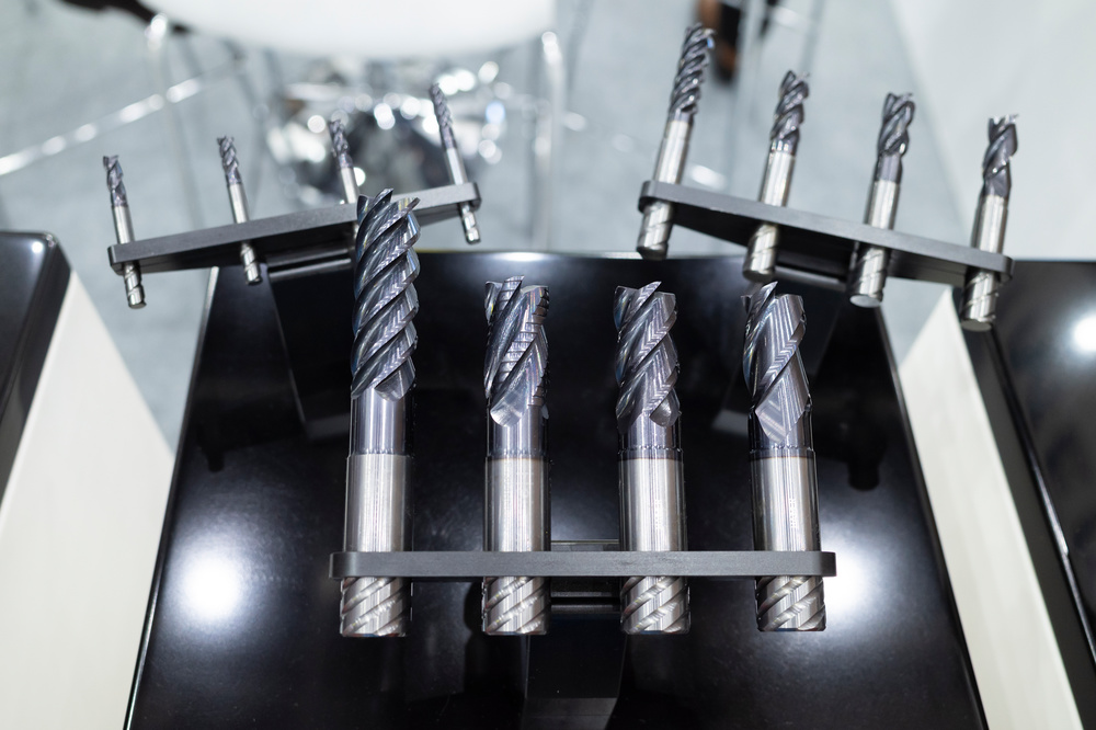
- Characteristics: Stronger cutting edges, lower cutting forces
- Advantages: Better for hard materials, reduced deflection
- Applications: Steel, stainless steel, deep slotting
- Recommended Materials: Ferrous materials, hard materials
- Characteristics: Balanced cutting performance
- Advantages: Versatile, good for general purpose
- Applications: General machining, mixed materials
- Recommended Materials: All materials, general purpose
- Characteristics: Aggressive cutting, excellent chip evacuation
- Advantages: High material removal rates, good for soft materials
- Applications: Aluminum, brass, plastics
- Recommended Materials: Non-ferrous materials, soft materials
4.2 Number of Flutes
- Characteristics: Large chip gullets, excellent chip evacuation
- Advantages: Best for aluminum and soft materials
- Applications: Aluminum machining, roughing, slotting
- Surface Finish: Moderate to good
- Characteristics: Balanced chip evacuation and rigidity
- Advantages: Good for aluminum and some ferrous materials
- Applications: Aluminum, general purpose, finishing
- Surface Finish: Good to excellent
- Characteristics: Good rigidity, better surface finish
- Advantages: Versatile, good for most materials
- Applications: Steel, stainless steel, general purpose
- Surface Finish: Excellent
- Characteristics: Maximum rigidity, best surface finish
- Advantages: Excellent for finishing operations
- Applications: Finishing, hard materials, precision machining
- Surface Finish: Superior
4.3 Cutting Edge Geometry
- Positive Rake Angle: Better for soft materials, lower cutting forces
- Neutral Rake Angle: Balanced performance, general purpose
- Negative Rake Angle: Better for hard materials, increased edge strength
- Primary Clearance Angle: Reduces friction between tool and workpiece
- Secondary Clearance Angle: Provides additional support
- Typical Values: 5-15° depending on material
- Sharp Corner: Maximum precision, prone to chipping
- Small Radius (0.1-0.2mm): Balanced precision and strength
- Medium Radius (0.2-0.5mm): Good for most applications
- Large Radius (0.5-1.0mm): Maximum strength, reduced precision
4.4 Shank and Neck Design
- Straight Shank: Most common, standard interface
- Weldon Shank: For high-torque applications
- Reduced Shank: Larger cutting diameter than shank diameter
- Taper Shank: For heavy-duty applications
- Standard Neck: Straight design, general purpose
- Reduced Neck: Increased reach, reduced rigidity
- Long Neck: Maximum reach for deep cavities
- Tapered Neck: Improved rigidity for deep cuts
5. Material-Specific Selection Guide
5.1 Aluminum and Non-Ferrous Materials
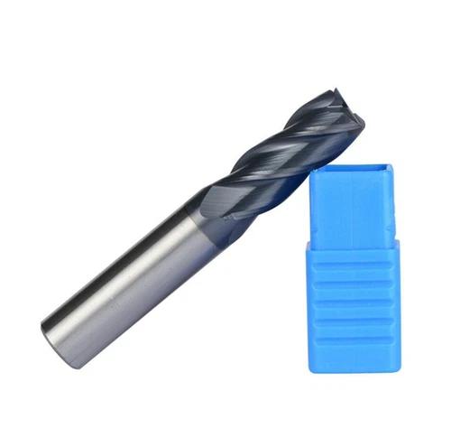
- Material: Carbide (micrograin)
- Coating: TiN, ZrN, or uncoated
- Flute Count: 2 or 3 flutes
- Helix Angle: 40-45° (high helix)
- Cutting Edge: Sharp, polished
- Chip Gullet: Large for chip evacuation
- Cutting Speed: 1000-3000 SFM
- Feed Rate: 0.001-0.003 IPR per flute
- Depth of Cut: Up to 2x diameter for roughing
- Coolant: High-pressure coolant recommended
- Built-Up Edge: Use polished flutes and proper coolant
- Chip Evacuation: Large flute design and high helix angle
- Vibration: Rigid setup and proper tool length
5.2 Steel and Carbon Steels
- Material: Carbide (fine grain)
- Coating: TiAlN or AlTiN
- Flute Count: 4 flutes
- Helix Angle: 30-35° (medium helix)
- Cutting Edge: Moderate sharpness
- Core Diameter: Large for rigidity
- Cutting Speed: 300-1000 SFM
- Feed Rate: 0.0005-0.002 IPR per flute
- Depth of Cut: Up to 1.5x diameter for roughing
- Coolant: Flood coolant required
- Heat Generation: Use heat-resistant coatings
- Tool Wear: Proper cutting parameters and coatings
- Chip Control: Optimized flute geometry
5.3 Stainless Steel
- Material: Carbide (fine grain)
- Coating: TiAlN or AlTiN
- Flute Count: 4 or 5 flutes
- Helix Angle: 35-40°
- Cutting Edge: Strong, negative rake
- Chip Gullet: Medium size
- Cutting Speed: 100-300 SFM
- Feed Rate: 0.0005-0.0015 IPR per flute
- Depth of Cut: Up to 1x diameter for roughing
- Coolant: High-pressure coolant recommended
- Work Hardening: Use higher feed rates
- Heat Generation: Lower cutting speeds, good coolant
- Chip Control: Proper flute design and cutting parameters
5.4 Titanium and Titanium Alloys
- Material: Carbide (ultra-fine grain)
- Coating: AlTiN or TiAlN
- Flute Count: 4 flutes
- Helix Angle: 35-40°
- Cutting Edge: Rounded corners, strong design
- Core Diameter: Large for rigidity
- Cutting Speed: 50-150 SFM
- Feed Rate: 0.0005-0.0015 IPR per flute
- Depth of Cut: Up to 0.5x diameter for roughing
- Coolant: Flood coolant required
- Heat Generation: Low cutting speeds, effective cooling
- Tool Wear: Premium coatings and carbide grades
- Vibration: Rigid setup, proper tool length
5.5 Composites and Advanced Materials
- Material: Carbide with diamond coating
- Coating: Diamond or DLC (Diamond-Like Carbon)
- Flute Count: 2 or 3 flutes
- Helix Angle: 40-45°
- Cutting Edge: Sharp, polished
- Chip Gullet: Large for chip evacuation
- Cutting Speed: 500-2000 SFM
- Feed Rate: 0.0005-0.002 IPR per flute
- Depth of Cut: Up to 1x diameter
- Coolant: Compressed air or minimum quantity lubrication
- Delamination: Sharp cutting edges, proper feed rates
- Tool Wear: Diamond coatings
- Heat Generation: Proper cooling strategy
6. Cutting Parameters Optimization
6.1 Spindle Speed Calculation
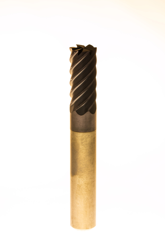
- Cutting Speed: 1500 SFM
- RPM = (1500 × 12) / (3.1416 × 0.3937) = 14,400 RPM
- Cutting Speed: 500 SFM
- RPM = (500 × 12) / (3.1416 × 0.5) = 3,820 RPM
6.2 Feed Rate Calculation
|
Material
|
Feed per Flute (IPR)
|
|
Aluminum
|
0.001-0.003
|
|
Carbon Steel
|
0.0005-0.002
|
|
Stainless Steel
|
0.0005-0.0015
|
|
Titanium
|
0.0005-0.0015
|
|
Cast Iron
|
0.0005-0.002
|
|
Composites
|
0.0005-0.002
|
6.3 Depth of Cut Recommendations
- Axial Depth of Cut: 1-2x tool diameter (depending on rigidity)
- Radial Depth of Cut: 20-50% of tool diameter
- Chip Thinning: Adjust feed rate for small radial depths
- Axial Depth of Cut: 0.002-0.010″ (0.05-0.25mm)
- Radial Depth of Cut: 0.001-0.005″ (0.025-0.125mm)
- Surface Finish: Adjust stepover for desired Ra value
6.4 Coolant Selection and Application
- Soluble Oil: General purpose, good lubricity
- Synthetic Coolants: High heat capacity, longer life
- Semi-Synthetic: Balanced performance
- Compressed Air: For composites and some dry machining applications
- Flood Cooling: Most common, general purpose
- High-Pressure Cooling: 1000+ PSI for deep holes and difficult materials
- Minimum Quantity Lubrication (MQL): Environmentally friendly option
- Through-Tool Cooling: Direct coolant to cutting zone
7. Tool Life Management and Optimization
7.1 Tool Wear Mechanisms
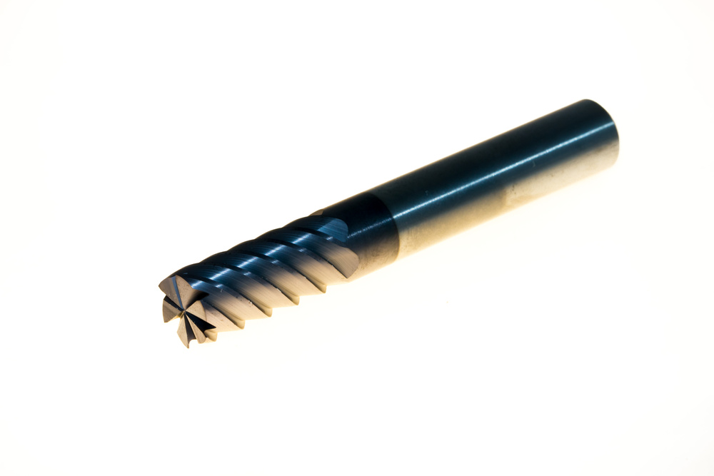
- Cause: Hard particles in workpiece material
- Symptoms: Gradual dulling of cutting edges
- Prevention: Harder tool materials, better coatings
- Cause: Material transfer from workpiece to tool
- Symptoms: Material buildup on cutting edges
- Prevention: Proper coatings, coolant, cutting parameters
- Cause: High cutting temperatures
- Symptoms: Discoloration, edge rounding
- Prevention: Heat-resistant coatings, proper coolant
- Cause: Chemical reactions between tool and workpiece
- Symptoms: Pitting, corrosion
- Prevention: Inert coatings, proper coolant
7.2 Tool Life Monitoring
- Edge Condition: Check for chipping, wear, built-up edge
- Flute Condition: Check for damage, wear, chip buildup
- Shank Condition: Check for runout, damage
- Cutting Forces: Increased forces indicate tool wear
- Vibration Levels: Increased vibration indicates dull tool
- Surface Finish: Deterioration indicates tool wear
- Cycle Time: Increased time indicates tool wear
7.3 Tool Storage and Handling
- Climate-Controlled Environment: Avoid moisture and temperature extremes
- Proper Organization: Labeled storage system
- Protection: Use original packaging or protective sleeves
- Cleaning: Regular cleaning of tools and storage areas
- Proper Gripping: Avoid touching cutting edges
- Clean Installation: Clean tool holders and shanks
- Torque Control: Proper tightening torque
- Runout Control: Minimize runout during installation
7.4 Cost Optimization Strategies
- Initial Tool Cost: Purchase price
- Tool Life: Number of parts per tool
- Machine Time: Cycle time per part
- Labor Costs: Setup and operation time
- Scrap Costs: Defective parts due to tool issues
- Optimal Tool Selection: Balance cost and performance
- Proper Maintenance: Extend tool life through proper care
- Process Optimization: Improve cutting parameters
- Volume Discounts: Take advantage of bulk purchasing
- Tool Rebuilding: Resharpen and recoat when economical
8. Troubleshooting Common Issues
8.1 Chatter and Vibration
- Tool Overhang: Excessive tool length
- Machine Rigidity: Insufficient rigidity
- Cutting Parameters: Improper speeds and feeds
- Tool Geometry: Inappropriate helix angle or flute count
- Reduce Tool Overhang: Use shorter tools or extensions
- Increase Rigidity: Improve fixturing, reduce overhang
- Adjust Parameters: Reduce cutting speed, increase feed rate
- Change Tool Geometry: Use lower helix angle, more flutes
8.2 Poor Surface Finish
- Tool Wear: Dull cutting edges
- Cutting Parameters: Improper stepover or feed rate
- Tool Geometry: Inappropriate flute count or helix angle
- Vibration: Chatter during machining
- Replace Tool: Use sharp tool
- Adjust Parameters: Optimize stepover and feed rate
- Change Tool: Use more flutes for finishing
- Reduce Vibration: Improve rigidity, adjust parameters
8.3 Tool Breakage
- Excessive Cutting Forces: Too much depth or feed
- Tool Overload: Improper tool selection
- Vibration: Chatter leading to fatigue failure
- Material Hardness: Workpiece harder than expected
- Reduce Cutting Forces: Decrease depth of cut, adjust feed rate
- Select Proper Tool: Use stronger tool geometry
- Reduce Vibration: Improve setup rigidity
- Adjust Parameters: Lower cutting speed for hard materials
8.4 Built-Up Edge
- Material Adhesion: Soft materials sticking to tool
- Insufficient Cooling: Poor coolant application
- Tool Material: Incompatible tool material
- Cutting Parameters: Too low cutting speed
- Change Coating: Use anti-stick coating
- Improve Cooling: Better coolant application
- Adjust Parameters: Increase cutting speed
- Polish Flutes: Smooth flute surfaces
9. Advanced Selection Considerations
9.1 High-Efficiency Milling (HEM)
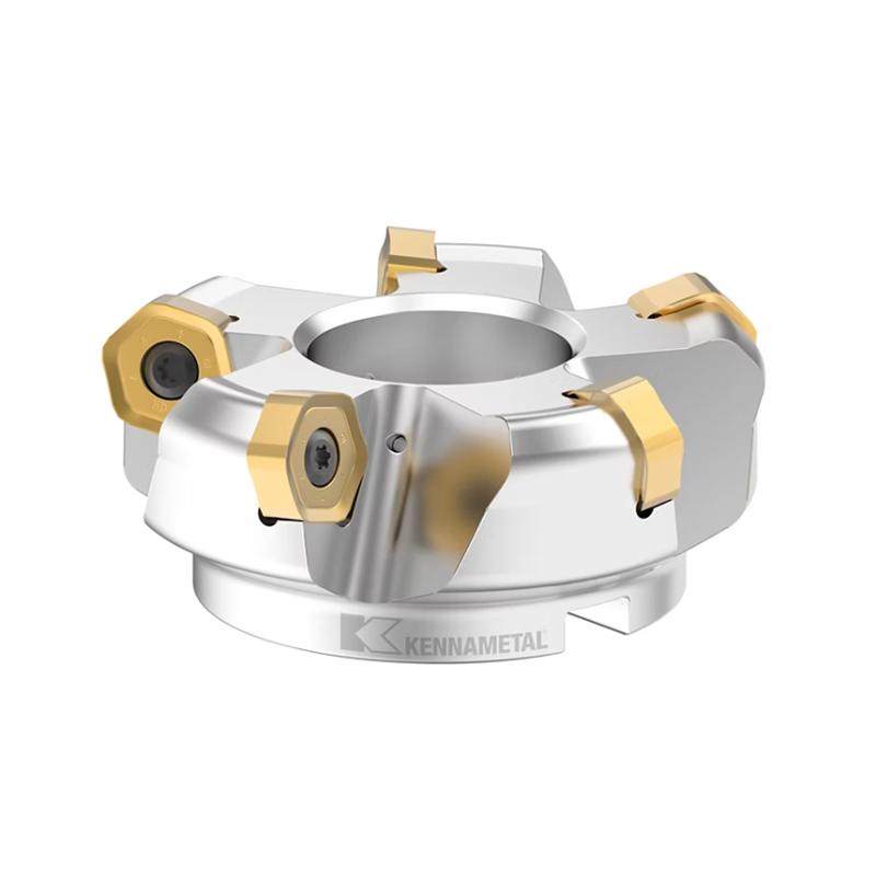
- Light Radial Depth: 10-20% of tool diameter
- Heavy Axial Depth: 2-3x tool diameter
- High Feed Rates: Optimized for chip thinning
- Trochoidal Toolpaths: Circular tool movements
- Material: Fine-grain carbide
- Coating: AlTiN or TiAlN
- Flute Count: 5-6 flutes
- Helix Angle: 40-45°
- Core Diameter: Large for rigidity
- Increased Productivity: 2-3x higher material removal rates
- Extended Tool Life: Reduced cutting forces and heat
- Improved Surface Finish: More consistent cutting action
- Reduced Machine Wear: Lower cutting forces
9.2 5-Axis Machining Considerations
- Tool Length: Longer tools for reach
- Rigidity: Increased rigidity for complex movements
- Chip Evacuation: Improved flute design for steep angles
- Collision Avoidance: Shorter tools when possible
- Reduced Neck: For clearance in complex geometries
- Ball Nose: For 3D contouring
- Tapered Design: For improved rigidity in deep cuts
- Special Coatings: For complex tool paths
9.3 Micro-Machining Applications
- Small Diameters: Down to 0.1mm or smaller
- High Precision: Tight tolerances
- Low Cutting Forces: To avoid workpiece damage
- Excellent Surface Finish: Mirror-like finishes
- Ultra-Fine Grain Carbide: For strength at small sizes
- Sharp Cutting Edges: For precision cutting
- Special Coatings: For improved performance
- Reduced Flute Count: For chip evacuation
9.4 Dry Machining Considerations
- Heat Resistance: Tools must withstand higher temperatures
- Friction Reduction: Low coefficient of friction
- Chip Control: Effective chip evacuation without coolant
- Material Compatibility: Some materials not suitable for dry machining
- Heat-Resistant Coatings: AlTiN, ceramic
- Special Geometries: Optimized for dry conditions
- Hard Tool Materials: Ceramic, CBN
- Surface Treatments: Reduced friction coatings
Conclusion: Developing Your End Mill Selection Strategy
Key Takeaways
- Match tool material to workpiece material properties
- Select appropriate coatings based on material and operation
- Consider heat resistance and wear properties
- Choose the right flute count for material and operation
- Select appropriate helix angle for cutting performance
- Consider corner radius for edge strength and surface finish
- Calculate optimal spindle speeds and feed rates
- Adjust depth of cut based on rigidity and tool strength
- Implement proper coolant strategies
- Consider total cost of ownership, not just initial price
- Implement tool life monitoring and optimization
- Develop preventive maintenance programs
- Monitor tool performance and make adjustments
- Stay updated on new tool technologies and materials
- Train personnel on proper tool selection and usage
Frequently Asked Questions (FAQ)
Q: How do I choose between carbide and HSS end mills?
Q: What coating is best for aluminum machining?
Q: How many flutes should my end mill have?
Q: What helix angle is best for my application?
Q: How do I calculate proper cutting speeds?
Q: What causes built-up edge and how can I prevent it?
Q: How can I extend tool life?
Q: What is the difference between roughing and finishing end mills?
Q: How do I choose between ball nose and square end mills?
Q: What factors affect surface finish in milling?
Disclaimer
- All information, opinions, and data contained in this article are for the purpose of information transmission only and do not constitute any advice on investment, transactions, law, medical care, or other matters.
- The content of the article is compiled based on public information or created based on the author’s personal understanding. Although every effort is made to ensure accuracy, it does not guarantee the completeness, accuracy, and timeliness of the information, nor does it bear any responsibility for any losses caused by the use of the content of this article.
- If the article involves third-party opinions, pictures, data, and other content, the copyright belongs to the original author. In case of infringement, please contact us for deletion.
- Readers should make independent decisions based on their actual situation and combined with professional opinions. The user shall bear all consequences arising from the use of the content of this article.


