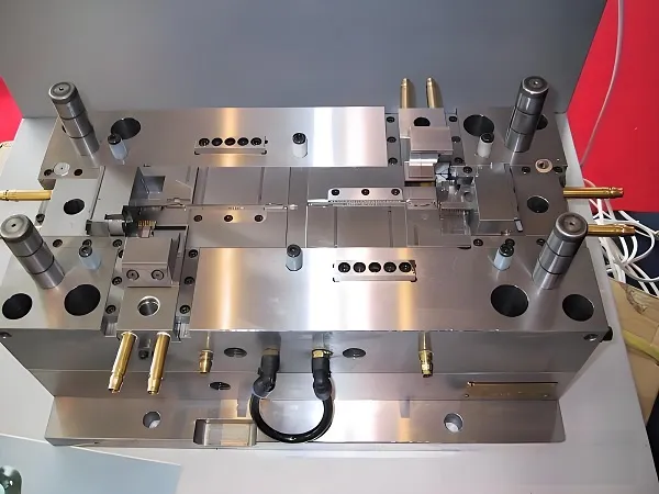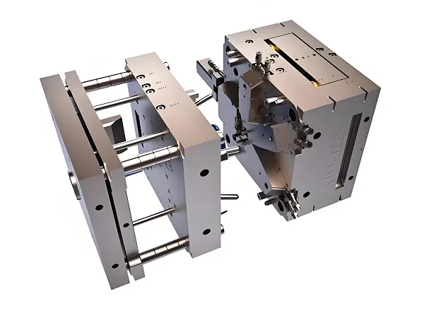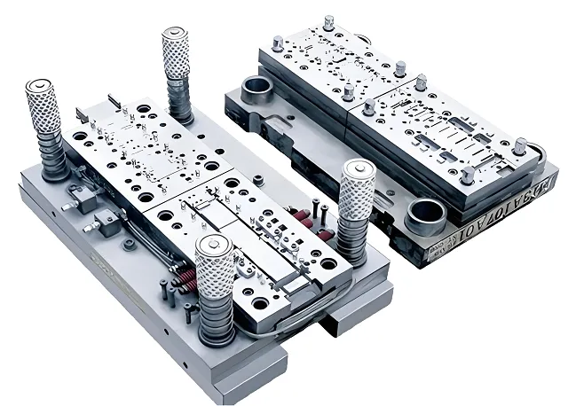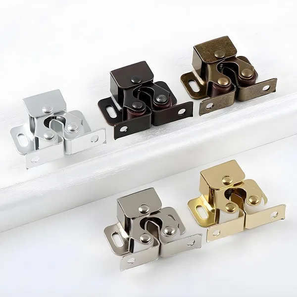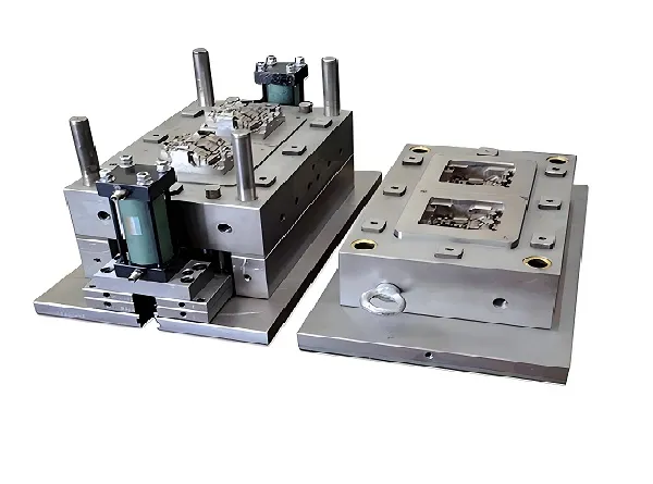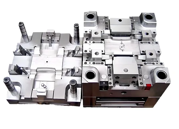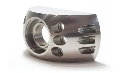
Core Cognition: CNC Machining Parts—More Than Metal, They’re “Industrial Building Blocks”
When you hold a smartphone’s aluminum frame, a jet engine’s titanium blade, or a medical device’s stainless steel housing, you’re holding a product of CNC machining. These parts aren’t just “pieces of metal”; they’re the invisible framework of modern life—each groove, hole, and contour engineered to fit, function, and last.
At its heart, CNC machining parts uses computer-controlled tools to remove material from raw stock (metal, plastic, composite) into precise shapes. The leap from manual machining to CNC isn’t just about speed—it’s about trust. A manual machinist might nail 9 out of 10 parts; CNC nails 999 out of 1000. That 0.1% difference is why CNC parts fly on rockets, keep hearts beating (in medical devices), and keep cars safe on highways.
But here’s the truth only those who’ve stood in front of a CNC machine know: Every part has a “personality.” A 7075 aluminum aerospace bracket demands patience (it chips easily); a PEEK plastic medical part demands care (it melts at high speeds); a 4140 steel gear demands respect (it dulls tools fast). CNC doesn’t eliminate the human touch—it amplifies it. You’re not just programming a machine; you’re guiding it to honor the material’s limits and the part’s purpose.
Industry data underscores this: CNC machining accounts for 75% of precision parts production globally (Source: 2025 Global CNC Machining Market Report), with automotive (32%), aerospace (25%), and medical (18%) as the top sectors. For these industries, “close enough” isn’t enough—a 0.005mm deviation in a turbine blade can mean the difference between smooth flight and disaster.
Core Services: The “Craftsman’s Toolkit” of CNC Machining Parts
CNC machining parts isn’t a single service—it’s a family of techniques, each tailored to different part needs. Choosing the right one isn’t just about technicality; it’s about knowing what the part needs to be.
A. CNC Milling: For Complex Contours (The “Sculptor’s Art”)
- What It Does: Uses rotating end mills to cut 2D/3D shapes—slots, pockets, arcs, and complex surfaces—on stationary workpieces. Ideal for parts with irregular shapes (e.g., engine brackets, smartphone frames).
- Key Capabilities: 3-axis (simple shapes) to 5-axis (complex, multi-angle parts like aerospace impellers). 5-axis milling can reach angles no other method can—like a sculptor who can carve every side of a stone without moving it.
- Craftsman’s Insight: “When a client brings me a 3D model of an aerospace bracket with 45° angled holes, I reach for 5-axis milling. 3-axis would mean re-clamping the part 3 times—each clamp risks deviation. 5-axis does it in one pass, and the holes line up like they were drawn with a ruler. Saved me from a lot of late nights reworking parts.”
- Typical Materials: Aluminum (6061, 7075), steel (4140, 304), plastics (PEEK, ABS).
B. CNC Turning: For Rotational Parts (The “Potter’s Wheel”)
- What It Does: Spins the workpiece while a stationary tool cuts it into cylindrical shapes—shafts, bolts, bushings, and bearing rings. Think of it as a potter shaping clay on a wheel, but with micron-level precision.
- Key Capabilities: Lathes (simple turning) to turn-mill centers (combines turning with milling for parts like “shafts with keyways”).
- Craftsman’s Insight: “I once made 500 stainless steel bolts for a marine client. Turning them on a CNC lathe was a game-changer—each bolt had the exact same thread pitch, no wobbly heads. Before CNC, I’d spend hours filing down uneven heads. Now, the machine does the work, and I focus on making sure the first one is perfect.”
- Typical Materials: Steel (45#, 304), brass, aluminum (6061).
C. EDM (Electrical Discharge Machining): For “Impossible” Shapes (The “Magician’s Trick”)
- What It Does: Uses electrical sparks to erode metal—no physical cutting. Perfect for hard materials (tungsten, tool steel) or complex shapes with tiny details (e.g., mold cavities, micro-sized medical parts).
- Key Capabilities: Wire EDM (cuts through metal with a thin wire, like a laser) and Sinker EDM (creates internal shapes by “sinking” an electrode into the workpiece).
- Craftsman’s Insight: “A client once needed a mold with a 0.1mm-wide groove in tool steel—harder than a rock. Milling tools would snap like toothpicks. Wire EDM cut it like butter, and the groove was so smooth you could run your finger along it without feeling a bump. EDM isn’t just a service; it’s a way to make ‘impossible’ parts possible.”
- Typical Materials: Tool steel (H13), tungsten, titanium.
D. CNC Routing: For Large/Soft Materials (The “Carpenter’s Upgrade”)
- What It Does: Similar to milling, but for larger, softer materials—wood, foam, acrylic, and thin aluminum sheets. Used for signs, furniture parts, and prototyping.
- Key Capabilities: Large worktables (up to 2m×4m) for big parts; high-speed spindles for smooth cuts in soft materials.
- Craftsman’s Insight: “I make acrylic display cases for a jewelry brand. CNC routing lets me cut 10 cases at once, each with the same precise slots for shelves. Before CNC, I’d use a jigsaw, and the edges would be rough—now they’re so smooth I don’t need to sand them. The client loves it, and I save hours of work.”
- Typical Materials: Acrylic (PMMA), wood (plywood, MDF), foam (EPS), thin aluminum (<3mm).
Core Technologies: The “Brains” Behind Precise CNC Parts
CNC machining parts isn’t just about tools—it’s about the technologies that make precision possible. These aren’t just “features”; they’re the difference between a part that works and one that’s scrap.
A. CAD/CAM Integration: The “Design-to-Cut” Bridge
- How It Works: CAD (Computer-Aided Design) software (SolidWorks, AutoCAD) creates 3D models of the part; CAM (Computer-Aided Manufacturing) software (Mastercam, Fusion 360) converts the model into machine-readable G-codes.
- Emotional Resonance: “I once spent 3 days designing a custom gear in SolidWorks. When I imported it into Mastercam and saw the toolpath light up on the screen—every cut, every retract—I felt like I was watching a blueprint come to life. The CAM software doesn’t just generate code; it translates my design into a plan the machine can understand. No more hand-drawing toolpaths on paper.”
- Critical Tip: Always simulate the CAM toolpath before cutting. I once forgot to simulate a complex part and the tool collided with the fixture—ruined a $200 piece of aluminum. Now, simulation is non-negotiable.
B. Multi-Axis Machining: 3-Axis vs. 5-Axis (Precision on Steroids)
- 3-Axis Machining: Moves in X, Y, Z axes—good for simple parts (e.g., flat brackets, holes in a plate). Limitation: Can’t reach angles or undercuts.
- 5-Axis Machining: Adds A (rotation around X) and B (rotation around Y) axes—can cut every side of a part in one setup. Used for aerospace, medical, and racing parts.
- Data Support: 5-axis machining reduces setup time by 60% and error rates by 75% compared to 3-axis for complex parts (Source: 2025 CNC Multi-Axis Technology Report).
- Craftsman’s Insight: “I machined a titanium aerospace blade on a 5-axis machine last year. The blade has a curved surface that changes angle every few millimeters. With 3-axis, I would have needed 4 setups—and each setup risked shifting the part. With 5-axis, it took one setup, and the blade’s dimensions were perfect. I still have the first blade I made—it’s a reminder of what 5-axis can do.”
C. Real-Time Monitoring: The “Guardian Angel” of CNC Parts
- How It Works: Sensors on the machine track cutting force, temperature, and tool wear. If something goes wrong (e.g., tool dulls, material shifts), the machine pauses automatically.
- Example: A sensor detects that the cutting force is 20% higher than normal—sign the tool is dull. The machine stops, alerts the operator, and saves the part from being ruined.
- Craftsman’s Insight: “Real-time monitoring saved me during a batch of 100 aluminum brackets. Halfway through, the sensor noticed the tool was wearing down—if it had kept going, the next 50 brackets would have had rough surfaces. I changed the tool, and the rest of the batch was perfect. It’s like having a second pair of eyes watching every cut.”
D. Quality Control (QC) Technologies: The “Final Check”
- Tools: Coordinate Measuring Machines (CMM) for 3D precision checks; calipers, micrometers, and thread gauges for basic measurements.
- Process: Every batch has a “first article inspection” (FAI)—check the first part’s dimensions against the CAD model. If it’s good, run the batch; if not, fix the issue.
- Craftsman’s Insight: “I once skipped FAI to save time—and regretted it. The batch of 200 bolts had the wrong thread pitch. I had to scrap all of them, cost me $1,500 and a client’s trust. Now, FAI is the first thing I do. It’s not a ‘step’—it’s a promise to the client that their parts are right.”
Practical Case: Machining a 7075-T6 Aluminum Aerospace Bracket
Let’s walk through a project that’s close to my heart: making 50 7075-T6 aluminum brackets for a small aerospace startup. The part is 100×50×10mm, with 4×φ6mm holes (position tolerance ±0.005mm) and a 3mm-deep pocket (surface roughness Ra≤1.6μm). This isn’t just “machining a bracket”—it’s machining something that might one day fly.
Step 1: Material Prep—Respect the Metal
7075-T6 is tough: high strength (used in airplane wings) but prone to chipping. I ordered 50 pieces of 105×55×12mm 7075-T6 stock (extra material for machining). First, I cleaned the stock with isopropyl alcohol—oil or dirt can throw off measurements.
Step 2: CAD/CAM Setup—Plan Every Cut
- CAD: Used SolidWorks to create a 3D model of the bracket, marking the holes and pocket with tolerances.
- CAM: Imported the model into Mastercam. Set up the toolpath:
-
- Face mill the top surface to 10mm thickness (use a 20mm carbide face mill, S3000r/min, F500mm/min).
-
- Mill the 3mm-deep pocket (use a 10mm 4-flute end mill, S4000r/min, F300mm/min—peck mill to avoid chip buildup).
-
- Drill the 4×φ6mm holes (use a φ6mm carbide twist drill, S2500r/min, F200mm/min—G83 peck cycle for deep holes).
- Simulation: Ran the toolpath simulation 3 times. Caught a potential collision between the end mill and the fixture—adjusted the toolpath to avoid it.
Step 3: Machining—Steady Hands, Calm Mind
- Machine: Used a Haas VF-5 5-axis milling center (reliable for aerospace parts).
- Fixture: Clamped the stock in a precision vice with soft jaws (avoids scratching the aluminum). Checked the vice alignment with a dial indicator—max runout 0.001mm.
- First Cut: Ran the first bracket. The machine hummed smoothly—no squealing (a sign of good tool selection). When it finished, I held the bracket up to the light—no visible burrs, the pocket looked smooth.
Step 4: QC—The Moment of Truth
- CMM Check: Measured the first bracket with a Zeiss CMM. The holes were at (20,20), (20,40), (80,20), (80,40)—all within ±0.003mm. The pocket depth was 3.001mm, Ra=1.4μm. Perfect.
- Batch Run: Ran the next 49 brackets. Checked every 10th part with a micrometer—all dimensions held.
- Client Delivery: When I handed the brackets to the startup’s engineer, he said, “These are better than the ones we get from big manufacturers.” That comment meant more than any paycheck.
Common Nightmares (and How to Fix Them)
Every CNC machinist has horror stories—parts that cracked, tools that broke, deadlines that loomed. But these aren’t “failures”; they’re lessons in disguise.
1. Part Cracks During Machining (Aluminum/Steel)
- Cause: Too much cutting force (feed rate too high) or material stress (stock wasn’t annealed). I once cracked a 7075-T6 bracket because I set F=400mm/min instead of 300—too much force pulled the metal apart.
- Solution: Reduce feed rate by 20-30%; anneal the material (heat-treat to release stress) before machining. For 7075-T6, anneal at 343°C for 2 hours.
2. Surface Roughness Ra > Requirement (All Materials)
- Cause: Dull tool, low spindle speed, or insufficient coolant. I had a batch of acrylic parts with Ra=3.2μm—turned out the end mill was dull (the cutting edge had tiny chips).
- Solution: Replace the tool; increase spindle speed by 10-15%; check coolant flow (ensure it covers the cutting zone). For acrylic, use compressed air instead of liquid coolant—no residue, smoother surface.
3. Hole Position Deviation (±0.01mm Instead of ±0.005mm)
- Cause: Fixture alignment off, or spindle runout too high. I once had this issue with stainless steel parts—found the vice was tilted 0.002mm.
- Solution: Realign the fixture with a dial indicator (max runout 0.001mm); calibrate the spindle (replace angular contact bearings if runout >0.002mm).
4. Tool Breakage (Small Diameter <5mm)
- Cause: Excessive speed, feed rate too high, or chip clogging. I broke a φ3mm carbide drill in aluminum—speed was 8000r/min (too high), chips clogged the flutes.
- Solution: Reduce speed by 30% (φ3mm aluminum: 5600r/min); use peck drilling (G83 Q2mm) to clear chips; use a tool with a larger flute area (2-flute instead of 3-flute for small drills).
Q&A: Wisdom from the Shop Floor
These are the questions I get asked most—from beginners just starting out to seasoned machinists looking for a fresh perspective.
Q1: “I’m a beginner—what’s the biggest mistake I should avoid?”
- My Answer: Rushing. I see beginners skip simulation, skip FAI, or use the wrong tool to save time. But time saved now is time lost later—scrapping parts, fixing machines, apologizing to clients. Slow down. Learn the material’s personality. Test the first part. I still take my time, even after 10 years. Precision isn’t a race—it’s a commitment.
Q2: “How do I choose between CNC milling and 3D printing for a part?”
- My Answer: Ask two questions: (1) Is the part metal or plastic? (2) Does it need strength? For metal parts or high-strength plastic (PEEK), CNC is better—3D printed metal is weaker, and 3D printed plastic can’t handle heavy loads. For small-batch, complex plastic prototypes (e.g., a toy part), 3D printing is faster. I had a client who wanted to 3D print a steel gear—we tested it, and it broke under load. We machined it instead, and it’s still working a year later.
Q3: “What’s the most important skill for a CNC machinist?”
- My Answer: Problem-solving. Machines break, tools dull, parts don’t turn out right. You can’t just hit “pause”—you need to figure out why. Once, my machine stopped mid-batch, and the error code was “spindle overload.” I checked the tool (dull), the material (dirty), and the fixture (loose)—turned out the fixture was loose. Fixed it, and the batch finished perfectly. Machinists aren’t just “button-pushers”—we’re detectives.
Q4: “How do I keep up with new CNC technologies (e.g., AI-driven machining)?”
- My Answer: Learn by doing. Take online courses (Mastercam University, Haas Training), talk to other machinists, and experiment with small projects. I recently tried AI-driven toolpath optimization—uploaded a CAD model, and the AI suggested a faster toolpath. It cut my cycle time by 15%. New tech isn’t scary—it’s a tool to make your work better. Just remember: AI can generate code, but it can’t replace your judgment.
Final Thought
CNC machining parts isn’t about machines—it’s about people. It’s about the engineer who designs a part to keep a plane safe, the machinist who cuts it with precision, and the end user who relies on it without ever knowing its story. Every part I make has a little piece of me in it: the time I spent calibrating the machine, the worry I felt during the first cut, the pride when it passes QC.
When you look at a CNC-machined part, don’t just see metal or plastic. See the hours of work, the lessons learned, and the commitment to excellence. That’s the real magic of CNC machining parts—not the technology, but the humans who use it to build a better world.
What part have you always wanted to machine? Or what’s a challenge you’ve faced with CNC parts? Share your story in the comments—I’d love to help you find a solution.


