I. What is CNC Machining Programming
On the precise stage of modern manufacturing, CNC machining programming is undoubtedly the behind-the-scenes protagonist, controlling the precise rhythm of production. Simply put, CNC machining programming is the use of a computer to write a series of instruction codes to precisely direct the operation of a CNC machine tool and complete the processing of various complex parts. For instance, a CNC machine tool is like a tireless craftsman, and programming is the detailed operation guide in the craftsman’s hand, precisely planning every minute movement from the tool’s movement path, cutting depth, to the spindle speed.
Broadly speaking, it is the crystallization of the deep integration of computer numerical control technology and mechanical processing technology, transforming the engineer’s design blueprint into a “language” that the machine tool can understand and execute. These programs not only determine the final shape and dimensional accuracy of the part but also directly affect production efficiency, processing costs, and product quality. In the aerospace field, for those parts with extremely demanding precision requirements, from engine blades to aircraft structural components, CNC machining programming enables the precise presentation of complex curved surfaces and high-precision holes. In automotive manufacturing, a large number of key components such as engine blocks and transmission gears rely on programming for efficient and mass production. It is no exaggeration to say that CNC machining programming has become the core supporting technology of modern manufacturing and is the key bridge connecting design and manufacturing, promoting industrial production towards high precision, high efficiency, and high flexibility.
II. Essentials for the Foundation of CNC Machining Programming
(1) Numerical Control System and Programming Language
The numerical control system, as the “brain” of a CNC machine tool, dominates every move of the machine tool. In the global market, the Japanese FANUC numerical control system occupies an important position in the medium and high-end fields with its high reliability and comprehensive specification series; the German SIEMENS numerical control system is known for its modular structure design and rich human-machine dialogue functions and is widely used in various types of precision processing machine tools.
In the field of programming, G codes and M codes are the most commonly used programming languages. G codes belong to the preparatory function codes and are mainly responsible for controlling the movement trajectory of the tool. For example, the G00 instruction can enable the tool to achieve rapid positioning and quickly move to the specified position, saving processing time; the G01 instruction is used for linear interpolation to make the tool precisely cut along a straight line, ensuring the accuracy of the machined linear contour. M codes are auxiliary function codes, mainly assisting the machine tool to complete some non-cutting actions. For instance, the M03 instruction can control the spindle to rotate forward, providing power for cutting processing; the M08 instruction can turn on the cutting fluid to cool the tool and workpiece and flush away the chips, extending the tool’s life and improving the processing surface quality.
(2) Coordinate System Analysis
The machine tool coordinate system is the inherent coordinate system of the machine tool, like the “basic map” of the machine tool. Its origin is set by the machine tool manufacturer and generally cannot be changed at will, serving as the reference benchmark for the machine tool’s movement. The workpiece coordinate system, on the other hand, is a temporary coordinate system artificially set by the programmer based on the processing requirements of the workpiece on the basis of the machine tool coordinate system, facilitating the programming and processing of workpieces of different shapes and positions.
When setting the workpiece coordinate system, instructions such as G54 – G59 are commonly used. For example, we set a certain feature point on the workpiece (such as the lower left corner vertex of the part) as the origin of the workpiece coordinate system. By measuring the coordinate value of this point in the machine tool coordinate system and inputting it into the G54 parameter of the numerical control system, subsequent programming can be based on this workpiece coordinate system, making the writing and understanding of the program more intuitive and simple. In actual processing, accurately setting the workpiece coordinate system is the key to ensuring processing accuracy, ensuring that the programmed tool path precisely corresponds to the actual position of the workpiece and avoiding processing deviations.
(3) Tools and Cutting Parameters
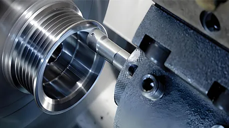
The selection of tools is like choosing the appropriate “weapon” for the processing task. Different types of tools are suitable for different processing scenarios. When processing the outer cylindrical surface, external turning tools are commonly used; for processing inner holes, internal turning tools are required; parting (grooving) turning tools are used for parting the workpiece or processing grooves; and thread turning tools are specifically for processing threads. When choosing tools, it is necessary to comprehensively consider the workpiece material, processing type, processing accuracy, and surface roughness requirements. When processing steel with high hardness, carbide tools should be selected; for parts with high processing accuracy and surface quality requirements, the geometric accuracy and edge quality of the tools should also be higher.
Cutting parameters include cutting speed, feed rate, and cutting depth, which are interrelated and mutually influential. The cutting speed is the linear speed of a certain point on the cutting edge of the tool relative to the workpiece, with the unit of m/min. If the cutting speed is too fast, the tool wear intensifies and may even lead to tool breakage; if it is too slow, the processing efficiency will be reduced. The feed rate is the relative displacement between the workpiece and the tool per revolution, with the unit of mm/r. If the feed rate is too large, the processing surface roughness will deteriorate; if it is too small, the processing time will be prolonged. The cutting depth refers to the vertical distance between the surface to be processed and the processed surface, with the unit of mm. In rough processing, to improve efficiency, the cutting depth can be appropriately increased; in finish processing, to ensure accuracy and surface quality, the cutting depth needs to be controlled to be smaller. In actual processing, it is necessary to reasonably determine the cutting parameters based on factors such as the workpiece material, tool performance, and machine tool power through experiments or referring to empirical data to achieve the best processing effect.
III. Comprehensive Analysis of the Programming Process
(1) Part Drawing Analysis
The part drawing is the “original blueprint” for processing, and conducting in-depth analysis of it is the primary task of programming. After obtaining the drawing, the first step is to carefully study the shape of the part. Whether it is a simple regular geometry or a complex free-form surface, its contour features need to be clearly defined. For complex curved surfaces such as aircraft engine blades, it is necessary to precisely grasp the mathematical description of curves and surfaces.
Dimensional accuracy is related to whether the part can perfectly fit with other components. For example, the aperture size of an automotive engine block has a very small tolerance and the processing error must be strictly controlled; surface roughness affects the surface quality and performance of the part. For critical components of medical devices, the surface is required to be extremely smooth to meet hygiene and functional requirements. At the same time, attention should also be paid to the material properties. The cutting performance of different materials varies greatly. When processing aluminum alloys and titanium alloys, the cutting parameters and tool selection are completely different. Through comprehensive analysis of the drawing, the processing key points and difficulties are clarified, providing an accurate basis for subsequent programming.
(2) Process Planning Formulation
Process planning is the key link in transforming the drawing into actual processing steps. Appropriate processing methods should be determined based on the shape, size, accuracy requirements, and material properties of the part. For example, milling is commonly used for planar processing, and methods such as drilling and boring can be used for hole processing.
There are also considerations for the processing sequence. Generally, the principle of “rough first, then fine; main first, then secondary; surface first, then hole” is followed. Rough processing is performed first to remove most of the allowance and improve processing efficiency; then finish processing is carried out to ensure dimensional accuracy and surface quality; the main surfaces are processed first to ensure the key dimensions and shape accuracy of the part; the plane is processed first to provide a stable positioning datum for subsequent hole processing.
The clamping method directly affects processing accuracy and stability. Appropriate fixtures and positioning methods should be selected to ensure that the workpiece is firmly and reliably during processing, avoiding displacement and vibration. The planning of the tool path is even more crucial. It is necessary to consider the tool’s entry and exit methods, avoid collisions and overcuts, and optimize the path to reduce idle strokes and improve processing efficiency. When processing complex molds, a reasonable tool path can significantly shorten the processing time and improve the mold surface quality.
(3) Writing the Machining Program
There are two methods for writing the machining program: manual programming and automatic programming. Manual programming is suitable for parts with simple shapes and small calculation amounts. Programmers need to manually write G codes and M code instructions based on the process planning. For example, when processing a simple rectangular part, by calculating the coordinate values of each vertex and writing the linear interpolation G01 instruction to control the tool movement, combined with M code instructions such as spindle speed and feed rate, the program writing is completed.
For complex parts, automatic programming with CAM software is more efficient and accurate. Taking Mastercam software as an example, first import the three-dimensional model of the part, then select the appropriate processing strategy, such as cavity milling, plane milling, etc., set the tool parameters and cutting parameters, and the software can automatically generate the tool path and convert it into a G code program recognizable by the machine tool through post-processing. In the aerospace field, the processing of complex components widely adopts automatic programming, which can quickly generate high-quality machining programs to meet high-precision processing requirements.
(4) Program Verification and Debugging
After the program is written, it cannot be directly used for actual processing and must undergo verification and debugging. Using simulation software, such as Vericut, the processing process can be simulated on a computer to visually observe whether the tool path is correct and check for any interference or collision between the tool and the workpiece or fixture. Through simulation, errors in the program can be discovered and corrected in advance to avoid workpiece scrapping or equipment damage during actual processing.
During actual machine tool debugging, first perform dry running to observe whether the movement of each axis of the machine tool is normal and check for program syntax and logical errors. Then conduct the first-piece trial cutting, measure the dimensions and perform quality inspection of the machined part, and fine-tune the program parameters such as cutting speed and feed rate based on the inspection results to further optimize the program to ensure the quality and efficiency of subsequent batch processing. In the production of automotive parts, the first-piece trial cutting and program optimization are key links to ensure the consistency of product quality.
IV. The Relationship between CNC Programming and CNC Machining
CNC programming and CNC machining are two closely linked and mutually reinforcing key links in modern manufacturing, jointly promoting the development of precision manufacturing.
Essentially, CNC programming is the “brain” and “soul” of CNC machining, providing precise instructions and planning for the processing process. Programmers carefully write the machining programs based on the design requirements and processing technology of the part, determining key elements such as the tool’s movement path, cutting parameters, and processing sequence. These programs are like a detailed construction blueprint, guiding the CNC machine tool to complete the processing task methodically. When processing complex aircraft engine impellers, CNC programming precisely plans the tool’s movement path in three-dimensional space, enabling the impeller blades to be precisely machined to meet the strict requirements of high precision and high performance of aircraft engines.
CNC machining, on the other hand, is the process of transforming the results of CNC programming into actual products, which is the specific execution link to realize the design intent. The CNC machine tool reads the program generated by programming and controls the movement of each coordinate axis of the machine tool, the rotation of the spindle, the feed of the tool, etc., and performs processing operations such as cutting, drilling, and milling on the workpiece, gradually processing the raw material into a part that meets the design requirements. In automotive component manufacturing, through CNC machining, raw metal materials are processed into key components such as engine blocks and crankshafts according to the parameters set in the programming to ensure the performance and quality of the vehicle.
The two influence and restrict each other. On the one hand, high-quality CNC programming is the prerequisite for achieving efficient and high-precision CNC machining. Reasonable programming can optimize the processing path, reduce the idle stroke of the tool, and improve processing efficiency; precise parameter settings can ensure processing accuracy and surface quality and reduce the scrap rate. If there are errors in programming, such as incorrect tool paths and unreasonable cutting parameters, it will lead to dimensional deviations and unqualified surface roughness of the machined parts, and even cause serious consequences such as tool damage and machine tool failure.
On the other hand, the actual situation in the CNC machining process will also provide feedback and adjustment requirements for CNC programming. During the processing, problems such as uneven hardness of the workpiece material and tool wear may be encountered. In this case, it is necessary to fine-tune the programming parameters based on the actual situation, such as adjusting the cutting speed and feed rate, to ensure the smooth progress of processing and the stability of part quality. In mold processing, due to the characteristics of the mold material and the heat accumulation during the processing, the tool wear may intensify. At this time, it is necessary to adjust the programming parameters, appropriately reduce the cutting speed, increase the supply of cutting fluid, extend the tool life, and ensure the processing accuracy of the mold.
V. Industry Applications
(1) Multi-Industry Application Examples
In the aerospace field, CNC machining programming is the core technology for manufacturing key components. The aircraft engine, as the “heart” of the aircraft, its blade processing is an ultimate challenge. The blade shape is complex, presenting a twisted three-dimensional curved surface, and has extremely high precision requirements, with the tolerance needing to be controlled within a very small range, usually within ±0.01mm. Through CNC machining programming and the use of five-axis linkage processing technology, the tool can move simultaneously in five coordinate axis directions to precisely cut the complex shape of the blade, ensuring a smooth blade surface and precise contour to meet the efficient and stable operation requirements of the engine in high-temperature, high-pressure, and high-speed rotation environments. For example, the new type of aircraft engine of the US-based GE Company has significantly improved the fuel efficiency and thrust of the engine with the aid of advanced CNC machining programming.
In automotive manufacturing, CNC machining programming is everywhere, from engine blocks to transmission gears. Taking the engine block as an example, it has a complex structure with multiple cylinder bores, water channels, oil channels, etc. During processing, through precise CNC programming, the machining center can successively complete multiple processes such as milling, drilling, and boring, precisely controlling the size and position accuracy of each bore to ensure the sealing of the cylinder and the smooth movement of the piston. On the engine production line of Volkswagen, advanced CNC machining technology is adopted to achieve efficient and high-precision batch production of engine blocks, significantly improving production efficiency and product quality consistency.
In the field of medical devices, CNC machining programming provides a strong guarantee for patients’ health. When manufacturing orthopedic implants, such as hip replacement prostheses, personalized customization is required based on the patient’s bone structure and size. Through 3D scanning to obtain the patient’s bone data, generating a CAD model, and then using CNC machining programming to precisely control the machine tool for processing, biocompatible materials such as titanium alloys are processed into prostheses that perfectly fit the patient’s bones. Some high-end medical device manufacturers in Switzerland, relying on advanced CNC machining programming technology, produce high-precision and high-biocompatibility orthopedic implants, helping numerous patients recover their health.
VI. Common Problems and Solutions
(1) Overcut and Undercut Problems
Overcut refers to the tool cutting to areas that should not be cut, resulting in excessive removal of workpiece material, affecting the dimensional accuracy and surface quality of the part. In severe cases, the workpiece is directly scrapped; undercut means the tool fails to cut to the预定 position, leaving excess material, also causing the part size to not meet the requirements.
Improper tool selection is a common cause. Insufficient tool strength, being too long or too small, is prone to tool springing under the action of cutting force, leading to overcut; the shape of the tool’s cutting part does not match the workpiece surface. For example, if the ball head diameter of a finger-shaped milling cutter is larger than the minimum arc diameter of the surface, overcut will occur; if it is smaller than the minimum arc diameter, undercut may occur. Unreasonable cutting parameters can also cause problems. Excessive cutting speed and feed rate cause a sharp increase in the tool’s force, prone to overcut; improper setting of the cutting depth may lead to undercut. Insufficient workpiece rigidity, resulting in displacement or deformation under the action of cutting force, can also cause overcut or undercut.
To solve this, it is necessary to strictly follow the tool selection standards, choosing larger rather than smaller and shorter rather than longer to enhance the tool’s rigidity. Select the tool precisely based on the workpiece shape and processing requirements to ensure the tool shape matches the workpiece surface. Adjust the cutting parameters reasonably, such as rounding the corners with a large allowance to avoid sudden changes in cutting force; utilize the SF function of the machine tool to allow the operator to adjust the rate based on the actual cutting situation to achieve a good cutting effect for the machine tool. For workpieces with poor rigidity, adopt an appropriate clamping method and auxiliary support to enhance their rigidity.
(2) Tool Collision Problem
Tool collision refers to the collision of the tool with the workpiece, fixture, or machine tool components, which can damage the tool, workpiece, and even the machine tool, affecting processing accuracy and production progress.
Incorrect setting of the safe height is a common cause. If the safe height is set too low, the tool may collide with the workpiece or fixture during rapid movement or tool lifting. Program errors, such as incorrect coordinate setting, unreasonable process arrangement, and incorrect tool path planning, can also lead to tool collision. Incorrect tool measurement, incorrect input of tool setting data, and too short tool installation, causing the actual position of the tool to not match the program setting, triggering tool collision. The blank size exceeds expectations and does not match the blank set in the program. When the tool moves, it is prone to colliding with the excess material.
To prevent tool collision, after writing the program, carefully check the tool path and use simulation software for processing simulation to discover and correct potential problems in advance. Set a reasonable safe height to ensure that the safe height is greater than the clamping height. In most cases, avoid choosing the “direct” tool entry and exit method. Accurately measure the tool, use scientific measuring instruments, and the tool installation length should be 2 – 5mm longer than the actual depth. Before processing, carefully check the program and workpiece information, including the program number, program content, blank size, etc.
(3) Precision Error Problem
Processing precision error refers to the deviation degree between the actual geometric parameters of the machined part and the ideal geometric parameters, directly affecting the assembly and performance of the part.
Machine tool accuracy is a key factor. The manufacturing errors, installation errors and wear during use of the machine tool, such as spindle rotation error, guide rail error and transmission chain error, will all be transferred to the workpiece, affecting the processing accuracy. Tool wear will change the shape and size of the tool’s cutting edge, leading to processing size deviation; insufficient installation accuracy of the tool and runout of the cutting edge will also affect the processing accuracy. The positioning and clamping errors of the workpiece make the position of the workpiece inaccurate during the processing, resulting in processing accuracy errors. Cutting heat and cutting force will cause thermal deformation and force deformation of the workpiece and the tool, leading to processing size and shape errors.
It is necessary to conduct regular accuracy inspection and maintenance of the machine tool, timely adjust and repair worn parts to ensure the accuracy of the machine tool. Select tools reasonably according to the processing requirements and workpiece materials, and replace worn tools in time; improve the installation accuracy of the tools to ensure the rotational accuracy of the cutting edge. Optimize the positioning and clamping methods of the workpiece, adopt high-precision fixtures to ensure the stability and accuracy of the workpiece during the processing. Reasonably control the cutting parameters to reduce the generation of cutting heat and cutting force; adopt cooling and lubrication measures to reduce the cutting temperature and reduce thermal deformation.

