Introduction
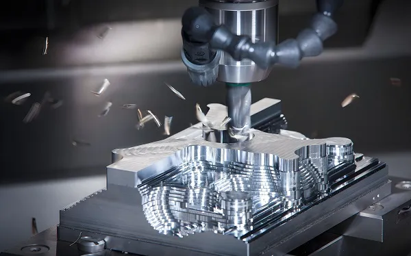
Computer Numerical Control (CNC) milling is a fundamental subtractive manufacturing process that has revolutionized modern manufacturing. This comprehensive guide explores the theoretical foundations of CNC milling, covering kinematic principles, cutting mechanics, machine dynamics, and advanced control strategies. Understanding these theoretical concepts is essential for achieving optimal machining performance, ensuring part quality, and maximizing process efficiency.
1. Theoretical Foundations of CNC Milling
1.1 Basic Principles of Milling
Material Removal Mechanism:
CNC milling is a subtractive manufacturing process where a rotating cutting tool removes material from a stationary workpiece to create the desired geometry. The process involves three fundamental motions:
- Primary Motion: Rotation of the cutting tool (spindle rotation)
- Feed Motion: Linear movement of the workpiece relative to the tool
- Auxiliary Motions: Tool changes, coolant control, and spindle speed adjustments
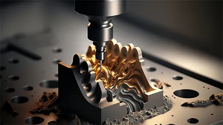
Cutting Mechanics:
The material removal process in milling involves complex interactions between the cutting tool and workpiece material:
- Shear Deformation: Material is removed through shear deformation in the primary shear zone
- Chip Formation: Material is transformed into chips through plastic deformation
- Heat Generation: Friction and plastic deformation generate heat at the cutting interface
- Tool Wear: Mechanical and thermal effects cause gradual tool wear
1.2 Kinematic Principles
Machine Kinematics:
CNC milling machines utilize a Cartesian coordinate system to control tool movements with high precision:
Linear Axes:
- X-Axis: Horizontal movement perpendicular to the spindle axis
- Y-Axis: Horizontal movement perpendicular to both X and Z axes
- Z-Axis: Vertical movement along the spindle axis
Rotary Axes (for multi-axis machines):
- A-Axis: Rotation around the X-axis
- B-Axis: Rotation around the Y-axis
- C-Axis: Rotation around the Z-axis
Coordinate Transformations:
The CNC system performs complex coordinate transformations to convert programmed positions into actual machine movements:
- Forward Kinematics: Converting joint motions to tool tip position
- Inverse Kinematics: Calculating required joint motions for desired tool position
- Coordinate System Offsets: Work offsets (G54-G59) and tool offsets
1.3 Machine Structure and Dynamics
Structural Components:
The mechanical structure of a CNC milling machine significantly influences its performance:
- Machine Base: Provides stable foundation and absorbs vibrations
- Column: Supports the spindle head and provides Z-axis movement
- Spindle Head: Houses the spindle and cutting tool
- Worktable: Supports the workpiece and provides X-Y movement
- Guideways: Provide precise linear motion guidance
Dynamic Behavior:
Machine dynamics play a critical role in machining performance:
- Stiffness: Resistance to deflection under cutting forces
- Damping: Ability to dissipate vibrational energy
- Natural Frequencies: Resonance characteristics that affect stability
- Thermal Behavior: Temperature-induced deformations
2. Cutting Tool Geometry and Mechanics
2.1 Tool Geometry Parameters
End Mill Geometry:
The geometric parameters of end mills directly influence cutting performance:
|
Parameter
|
Definition
|
Effect on Performance
|
|
Number of Flutes
|
Number of cutting edges
|
More flutes = higher feed rates but less chip evacuation
|
|
Helix Angle
|
Angle of flute relative to tool axis
|
Higher angles = better surface finish, lower angles = higher strength
|
|
Rake Angle
|
Angle of rake face relative to workpiece
|
Positive rake = better cutting, negative rake = higher strength
|
|
Clearance Angle
|
Angle of clearance face relative to cut surface
|
Prevents rubbing between tool and workpiece
|
|
Corner Radius
|
Radius at tool corner
|
Improves surface finish and tool life
|
|
Flute Length
|
Length of cutting portion
|
Determines maximum depth of cut
|
|
Overall Length
|
Total tool length
|
Determines reach and rigidity
|
Tool Materials:
Different tool materials are suited for various applications:
- High-Speed Steel (HSS): Good toughness, low cost, limited speed capability
- Carbide: High hardness, high speed capability, lower toughness
- Cermet: Combination of ceramic and metal, excellent wear resistance
- Ceramic: Very high temperature resistance, limited to specific materials
- Diamond: Ultimate hardness, for non-ferrous materials only
- CBN (Cubic Boron Nitride): For hard materials and high-speed machining
2.2 Cutting Mechanics and Forces
Cutting Force Components:
Three primary force components act on the cutting tool during milling:
- Axial Force (Fz): Force along the spindle axis
- Radial Force (Fr): Force perpendicular to the spindle axis
- Tangential Force (Ft): Force in the direction of tool rotation
Force Calculation:
Cutting forces can be estimated using empirical formulas:
**( F_c = K_c cdot A_c )
Where:
- ( F_c ) = Cutting force (N)
- ( K_c ) = Specific cutting force (N/mm²)
- ( A_c ) = Cross-sectional area of cut (mm²)
Chip Formation Mechanisms:
The chip formation process in milling involves several distinct regions:
- Primary Shear Zone: Initial deformation of material
- Secondary Shear Zone: Chip sliding along rake face
- Tertiary Shear Zone: Chip curling and breaking
2.3 Tool Wear and Life
Tool Wear Mechanisms:
Several mechanisms contribute to tool wear during milling:
- Abrasive Wear: Rubbing of hard particles against tool surface
- Adhesive Wear: Material transfer between tool and workpiece
- Diffusion Wear: Atomic diffusion between tool and workpiece
- Oxidation Wear: Chemical reaction with oxygen at high temperatures
- Thermal Cracking: Temperature-induced fatigue cracking
Tool Life Criteria:
Tool life is typically defined by:
- VB criterion: Average flank wear land width (usually 0.3-0.6 mm)
- Surface finish deterioration: When surface quality falls below requirements
- Noise or vibration: When abnormal cutting conditions occur
- Dimensional accuracy: When part dimensions exceed tolerances
Taylor’s Tool Life Equation:
Tool life can be predicted using Taylor’s equation:
**( V cdot T^n = C )
Where:
- ( V ) = Cutting speed (m/min)
- ( T ) = Tool life (min)
- ( n ) = Tool material exponent
- ( C ) = Material constant
3. Machining Parameters and Optimization
3.1 Cutting Parameters
Primary Parameters:
The three primary cutting parameters that influence milling performance are:
Cutting Speed (V):
- Definition: Surface speed of the tool relative to the workpiece
- Units: Meters per minute (m/min) or surface feet per minute (SFM)
- Calculation: ( V = pi cdot D cdot N / 1000 ) (for metric)
- Effect: Directly affects tool life and material removal rate
Feed Rate (f):
- Definition: Distance the tool moves per spindle revolution
- Units: Millimeters per revolution (mm/rev) or inches per revolution (ipr)
- Calculation: ( f = z cdot f_z ), where ( z ) = number of flutes, ( f_z ) = feed per flute
- Effect: Influences surface finish and cutting forces
Depth of Cut (ap):
- Definition: Thickness of material removed in one pass
- Units: Millimeters (mm) or inches (in)
- Types: Axial depth of cut (along Z-axis) and radial depth of cut (in X-Y plane)
- Effect: Affects cutting forces and tool deflection
3.2 Parameter Optimization Strategies
Material Removal Rate (MRR):
MRR is a key measure of machining efficiency:
**( MRR = v cdot f cdot a_p )
Where:
- ( v ) = Cutting speed (mm/min)
- ( f ) = Feed rate (mm/rev)
- ( a_p ) = Depth of cut (mm)
Optimization Objectives:
- Maximize MRR while maintaining quality
- Minimize production costs
- Maximize tool life
- Ensure process stability
Adaptive Control:
Modern CNC systems use adaptive control to optimize parameters in real-time:
- Constant Power Control: Maintains constant spindle power
- Constant Force Control: Maintains constant cutting force
- Tool Condition Monitoring: Adjusts parameters based on tool wear
- Vibration Monitoring: Prevents chatter by adjusting parameters
3.3 Machining Economics
Cost Analysis:
The total cost of machining includes several components:
- Tool Cost: Purchase price of cutting tools
- Machine Cost: Depreciation, maintenance, and energy consumption
- Labor Cost: Operator wages and benefits
- Material Cost: Cost of raw materials and scrap
- Overhead Cost: Facility, utilities, and administrative expenses
Economic Tool Life:
Optimal tool life that minimizes total production cost:
**( T_{opt} = sqrt[n]{frac{C_1 cdot (1 – n)}{C_2 cdot n}} )
Where:
- ( C_1 ) = Cost per tool change (including downtime)
- ( C_2 ) = Tool cost
- ( n ) = Taylor’s tool life exponent
4. CNC Milling Machine Structure and Components
4.1 Machine Configuration Types
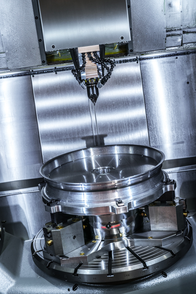
Vertical Milling Machines:
- Spindle axis is vertical
- Good for face milling, end milling, and drilling
- Better chip evacuation due to gravity
- More common for general-purpose machining
Horizontal Milling Machines:
- Spindle axis is horizontal
- Excellent for heavy cuts and large workpieces
- Better rigidity for high metal removal rates
- Common in automotive and aerospace industries
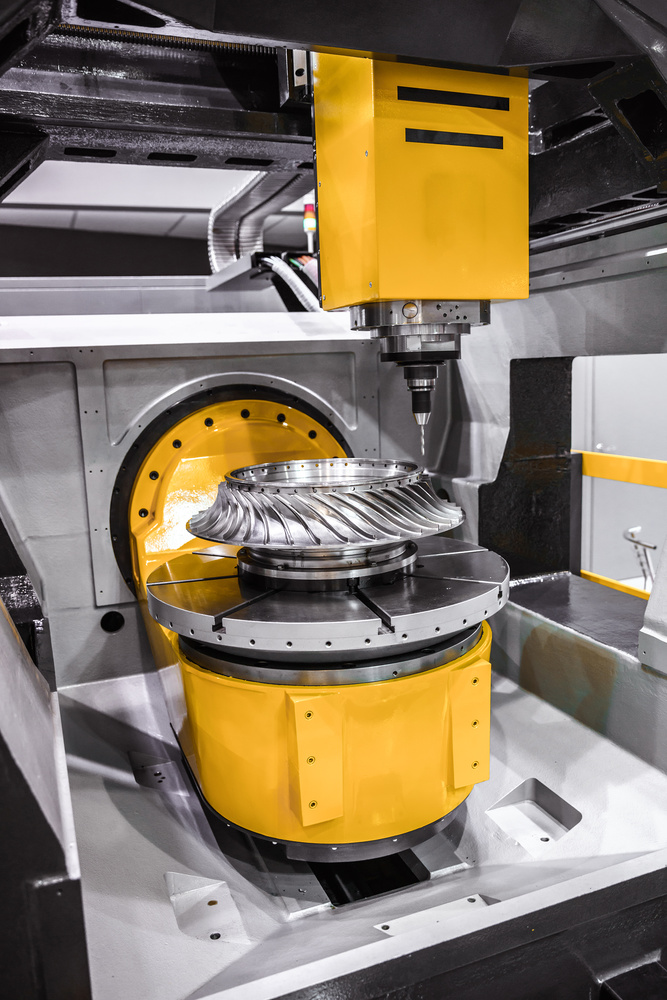
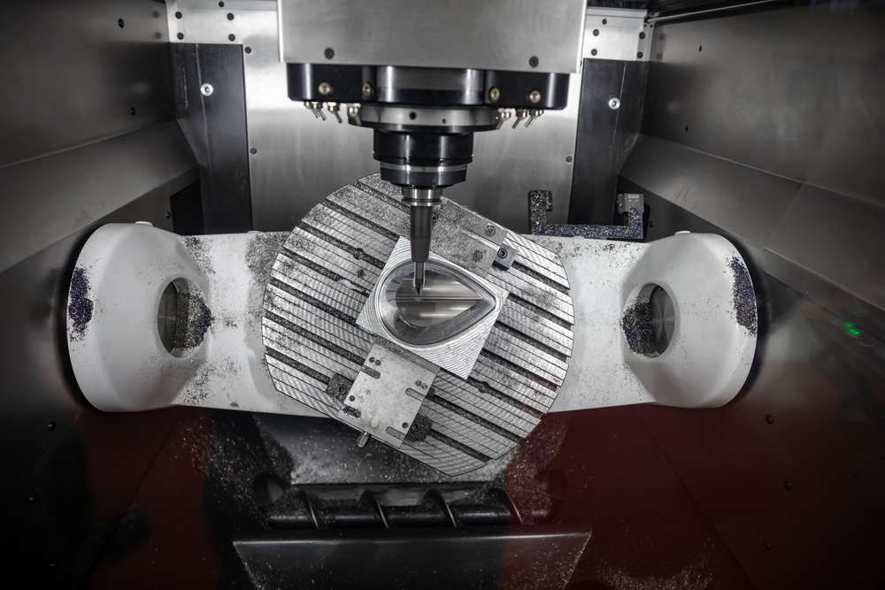
5-Axis Milling Machines:
- Combine 3 linear axes with 2 rotary axes
- Can machine complex 3D geometries in one setup
- Reduce setup time and improve accuracy
- Used for aerospace, medical, and mold making
4.2 Spindle Systems
Spindle Design:
The spindle is the heart of the milling machine:
- Spindle Bearings: Precision bearings for radial and axial support
- Spindle Motor: AC or DC motor for spindle rotation
- Spindle Speed Range: Typically 10-12,000 RPM for standard machines
- Spindle Taper: Standardized interface for tool holders (BT, CAT, HSK)
Spindle Performance Parameters:
- Speed Accuracy: Consistency of spindle speed under load
- Torque Characteristics: Torque output across speed range
- Rigidity: Resistance to deflection under cutting forces
- Thermal Stability: Minimization of heat-induced errors
4.3 Guideway Systems
Guideway Types:
Guideways provide precise linear motion:
- Box Way Guideways: High rigidity, good damping, more friction
- Linear Roller Guideways: Low friction, high speed, lower rigidity
- Linear Ball Guideways: Low friction, medium rigidity
- Hydrostatic Guideways: Zero friction, high precision, complex maintenance
Guideway Performance:
- Accuracy: Straightness and parallelism of motion
- Rigidity: Resistance to deflection
- Damping: Ability to absorb vibrations
- Wear Resistance: Long-term maintenance of accuracy
5. Control Systems and Programming
5.1 CNC Control System Architecture
Control System Components:
- Central Processing Unit (CPU): Main controller for machine operations
- Memory: Stores part programs and machine parameters
- Input/Output Interfaces: Communication with machine components
- Motion Controller: Generates axis motion commands
- Operator Interface: Display and input devices for operator interaction
Control Modes:
- Manual Mode: Direct operator control of machine movements
- MDI (Manual Data Input): Manual entry of program blocks
- Auto Mode: Automatic execution of part programs
- Edit Mode: Creation and modification of part programs
5.2 Programming Fundamentals
Coordinate Systems:
CNC milling uses several coordinate systems:
- Machine Coordinate System: Fixed to machine base
- Work Coordinate System: User-defined for each workpiece (G54-G59)
- Tool Coordinate System: Compensates for tool length and radius
- Relative Coordinate System: Temporary coordinate system
G-Code Programming:
G-codes control machine motion and functions:
|
G-Code
|
Function
|
Description
|
|
G00
|
Rapid Positioning
|
Fast movement to target position
|
|
G01
|
Linear Interpolation
|
Linear cutting movement
|
|
G02
|
Circular Interpolation CW
|
Clockwise circular motion
|
|
G03
|
Circular Interpolation CCW
|
Counterclockwise circular motion
|
|
G17/G18/G19
|
Plane Selection
|
Select XY, XZ, or YZ plane
|
|
G40/G41/G42
|
Tool Radius Compensation
|
Cancel, left, or right compensation
|
|
G43/G44
|
Tool Length Compensation
|
Apply positive or negative length offset
|
|
G90/G91
|
Absolute/Incremental Programming
|
Program coordinates relative to origin or current position
|
5.3 Advanced Programming Techniques
Subprograms:
- Reusable program segments called from main program
- Reduce program size and improve maintainability
- Implemented using M98 (call) and M99 (return)
Macro Programming:
- User-defined variables and arithmetic operations
- Conditional statements and loops
- Custom cycles for specific machining operations
CAM Programming:
- Computer-Aided Manufacturing software
- Automatic toolpath generation from CAD models
- Simulation and verification capabilities
- Optimization of cutting parameters
6. Error Analysis and Precision Control
6.1 Error Sources in CNC Milling
Geometric Errors:
- Straightness Errors: Deviation from straight line motion
- Flatness Errors: Deviation from flat surface
- Squareness Errors: Deviation from perpendicular axes
- Positioning Errors: Inaccuracies in final position
Thermal Errors:
- Spindle Growth: Thermal expansion of spindle
- Axis Deformation: Temperature-induced bending of machine components
- Guideway Expansion: Changes in guideway dimensions due to temperature
Dynamic Errors:
- Vibration: Relative motion between tool and workpiece
- Chatter: Self-excited vibrations during cutting
- Tool Deflection: Elastic deformation of cutting tool
- Workpiece Deflection: Elastic deformation of workpiece
6.2 Error Compensation Techniques
Software Compensation:
- Geometric Error Compensation: Corrects for machine geometry errors
- Thermal Error Compensation: Adjusts for temperature-induced errors
- Backlash Compensation: Corrects for mechanical backlash in drive systems
Hardware Compensation:
- Laser Interferometry: Precise measurement of positioning errors
- Ballbar Testing: Circular test for machine accuracy
- Renishaw Probing Systems: In-process measurement and correction
6.3 Precision Measurement and Metrology
Measurement Tools:
- Coordinate Measuring Machine (CMM): 3D measurement of part dimensions
- Laser Scanner: Non-contact 3D surface measurement
- Tool Presetter: Precise measurement of tool dimensions
- Touch Probe: In-machine measurement of workpiece position
Accuracy Standards:
- ISO 230: International standard for machine tool accuracy
- ASME B5.54: American standard for machine tools
- VDI/VDE 2617: German standard for machine accuracy
7. Advanced Milling Technologies
7.1 High-Speed Machining (HSM)
HSM Principles:
- High Spindle Speeds: Typically 15,000-40,000 RPM
- High Feed Rates: Up to 100 m/min
- Small Depth of Cut: 0.1-0.5 mm per pass
- High Surface Speeds: Optimized for specific materials
Benefits of HSM:
- Increased Productivity: Higher material removal rates
- Improved Surface Finish: Reduced cutting forces and vibrations
- Extended Tool Life: Optimal cutting conditions
- Reduced Heat Affected Zone: Lower cutting temperatures
HSM Requirements:
- High-Rigidity Machine: Stiff structure to handle dynamic forces
- High-Performance Spindle: Balanced for high speeds
- Advanced Cutting Tools: Specialized HSM tool materials
- High-Speed Control System: Fast processing and response
7.2 5-Axis Machining

5-Axis Kinematics:
- 3 Linear Axes: X, Y, Z for positioning
- 2 Rotary Axes: Typically A and C axes for orientation
- Tool Orientation: Ability to tilt tool to any angle
- Workpiece Orientation: Ability to rotate workpiece for optimal access
5-Axis Benefits:
- Single Setup Machining: Complete complex parts in one setup
- Improved Access: Reach all surfaces of complex geometries
- Reduced Fixturing: Less complex and expensive fixtures
- Improved Surface Finish: Better tool angles for finishing operations
Programming Challenges:
- Toolpath Generation: Complex 3D toolpath calculations
- Collision Detection: Prevention of tool and machine collisions
- Post-Processing: Specialized post-processors for machine kinematics
- Simulation: Verification of complex tool movements
7.3 Trochoidal Milling
Trochoidal Milling Principles:
- Circular Tool Path: Tool follows circular path while moving forward
- Low Radial Engagement: Tool engages only a small portion of its diameter
- Constant Cutting Load: Maintains consistent cutting forces
- High Material Removal Rate: Efficient use of cutting tool
Applications:
- Deep Slotting: Cutting deep slots without full width engagement
- High-Speed Machining: Reduced cutting forces enable higher speeds
- Hard Material Machining: Effective for materials up to 65 HRC
- Large Area Removal: Efficient roughing of large surfaces
8. Material-Specific Machining Considerations
8.1 Machining of Ferrous Metals
Carbon Steels:
- Cutting Speed: 100-300 m/min (HSS), 300-1000 m/min (carbide)
- Tool Material: Carbide, coated carbide
- Cutting Fluid: Emulsion, soluble oil
- Challenges: Built-up edge formation, heat generation
Alloy Steels:
- Cutting Speed: 80-250 m/min (HSS), 250-800 m/min (carbide)
- Tool Material: Coated carbide, cermet
- Cutting Fluid: Semi-synthetic, synthetic
- Challenges: Higher strength requires higher cutting forces
Stainless Steels:
- Cutting Speed: 50-200 m/min (HSS), 200-600 m/min (carbide)
- Tool Material: Coated carbide, CBN
- Cutting Fluid: High-pressure coolant, sulfurized oil
- Challenges: Work hardening, poor thermal conductivity
8.2 Machining of Non-Ferrous Metals
Aluminum Alloys:
- Cutting Speed: 300-1500 m/min (HSS), 1000-5000 m/min (carbide)
- Tool Material: Carbide, diamond
- Cutting Fluid: Soluble oil, air blast
- Challenges: Chip control, built-up edge
Copper Alloys:
- Cutting Speed: 100-500 m/min (HSS), 500-2000 m/min (carbide)
- Tool Material: Carbide, diamond
- Cutting Fluid: Soluble oil, synthetic
- Challenges: High thermal conductivity, stringy chips
Titanium Alloys:
- Cutting Speed: 10-50 m/min (HSS), 50-200 m/min (carbide)
- Tool Material: Carbide, coated carbide
- Cutting Fluid: High-pressure coolant, mineral oil
- Challenges: Low thermal conductivity, work hardening
8.3 Machining of Composite Materials
Carbon Fiber Composites:
- Cutting Speed: 100-500 m/min
- Tool Material: Diamond, carbide with special geometry
- Cutting Fluid: Water-based coolant, air blast
- Challenges: Fiber pullout, delamination, tool wear
Glass Fiber Composites:
- Cutting Speed: 50-300 m/min
- Tool Material: Carbide, diamond
- Cutting Fluid: Soluble oil, synthetic
- Challenges: Abrasive wear, heat generation
9. Surface Quality and Finish
9.1 Surface Finish Parameters
Surface Roughness Parameters:
- Ra (Arithmetic Average): Average deviation from mean line
- Rz (Ten-Point Average): Average of five highest peaks and five deepest valleys
- Rmax (Maximum Roughness): Maximum peak-to-valley height
- Rq (Root Mean Square): Root mean square of deviations
Surface Texture Characteristics:
- Lay Direction: Direction of machining marks
- Waviness: Longer wavelength deviations
- Flaws: Scratches, pits, or other imperfections
- Residual Stress: Stress state in surface layer
9.2 Factors Affecting Surface Finish
Cutting Parameters:
- Feed Rate: Primary factor affecting surface finish (Ra ∝ f²)
- Cutting Speed: Higher speeds generally improve finish
- Depth of Cut: Shallower cuts improve surface quality
- Tool Geometry: Rake angle, clearance angle, corner radius
Tool Condition:
- Tool Wear: Worn tools produce poorer finish
- Tool Material: Harder materials maintain better finish
- Tool Coating: Reduces friction and improves finish
- Tool Vibration: Causes chatter marks on surface
Machine Factors:
- Machine Rigidity: Stiffer machines produce better finish
- Spindle Runout: Minimizes eccentricity in cutting
- Guideway Precision: Affects motion accuracy
- Damping Characteristics: Reduces vibrations
9.3 Surface Finish Optimization
Finishing Strategies:
- Climb Milling: Produces better surface finish than conventional milling
- Ball Nose End Mills: For 3D surface finishing
- High-Speed Finishing: Optimized parameters for surface quality
- Tool Path Optimization: Smooth tool paths reduce surface irregularities
Advanced Finishing Techniques:
- High-Feed Milling: Special tools for high-speed finishing
- Trochoidal Finishing: Circular tool paths for uniform finish
- Vibration-Assisted Machining: Controlled vibrations to improve finish
- Laser-Assisted Machining: Heat-assisted cutting for difficult materials
10. Applications and Industry Trends
10.1 Key Industry Applications
Aerospace Industry:
- Complex Components: Turbine blades, engine casings, structural parts
- Material Requirements: Titanium, aluminum, composites, superalloys
- Tolerance Requirements: ±0.005-0.01 mm
- Surface Finish: Ra 0.4-1.6 μm
Automotive Industry:
- High-Volume Production: Engine components, transmission parts
- Material Requirements: Cast iron, aluminum, steel
- Tolerance Requirements: ±0.01-0.05 mm
- Surface Finish: Ra 1.6-6.3 μm
Medical Device Industry:
- Biocompatible Materials: Titanium, stainless steel, ceramics
- Complex Geometries: Implants, surgical instruments
- Tolerance Requirements: ±0.001-0.005 mm
- Surface Finish: Ra 0.1-0.8 μm
Electronics Industry:
- Miniaturized Components: Heat sinks, housings, connectors
- Material Requirements: Aluminum, copper, plastics
- Tolerance Requirements: ±0.005-0.02 mm
- Surface Finish: Ra 0.4-3.2 μm
10.2 Emerging Technologies and Trends
Industry 4.0 Integration:
- Smart Machining: Connected machines with IoT capabilities
- Big Data Analytics: Process optimization through data analysis
- Artificial Intelligence: Predictive maintenance and quality control
- Digital Twin: Virtual simulation of machining processes
Advanced Manufacturing Technologies:
- Additive-Subtractive Hybrid: Combining 3D printing with CNC milling
- Nanomanufacturing: Precision machining at nanoscale
- Green Machining: Environmentally friendly processes
- Robotic Machining: Collaborative robots in machining cells
Machine Technology Advancements:
- High-Precision Spindles: Nanoscale positioning accuracy
- Linear Motors: Direct drive systems for improved performance
- Advanced Sensors: Real-time monitoring of cutting conditions
- Adaptive Control Systems: Intelligent parameter adjustment
11. Conclusion and Future Directions
11.1 Summary of Key Theoretical Concepts
CNC milling machining theory encompasses a wide range of interdisciplinary concepts:
Fundamental Principles:
- Kinematic theory of machine tool motion
- Cutting mechanics and material removal processes
- Tool geometry and its influence on cutting performance
- Machine dynamics and structural behavior
Advanced Concepts:
- Multi-axis kinematics and coordinate transformations
- Error analysis and compensation techniques
- High-speed machining principles
- Material-specific machining characteristics
Practical Applications:
- Parameter optimization for different materials
- Surface finish control and improvement
- Precision measurement and quality assurance
- Industry-specific machining requirements
11.2 Future Research Directions
Technology Development Areas:
- Ultra-Precision Machining: Extending precision to nanoscale
- Intelligent Machining Systems: AI-driven process optimization
- Sustainable Manufacturing: Energy-efficient and environmentally friendly processes
- Multi-Material Machining: Advanced techniques for hybrid materials
Scientific Challenges:
- Material Behavior Modeling: Improved understanding of cutting mechanics
- Process Monitoring: Real-time sensing and control
- Tool Wear Mechanisms: Fundamental understanding of wear processes
- Machine Dynamics: Advanced modeling and control of dynamic behavior
11.3 Practical Implications for Industry
Manufacturing Excellence:
- Process Optimization: Applying theoretical knowledge to improve productivity
- Quality Improvement: Using scientific principles to enhance part quality
- Cost Reduction: Optimizing processes to minimize production costs
- Innovation: Developing new applications based on theoretical understanding
Workforce Development:
- Technical Education: Integrating theoretical concepts into training programs
- Skill Enhancement: Continuous learning for technological advancements
- Problem-Solving: Applying theoretical knowledge to practical challenges
- Adaptability: Preparing for emerging technologies and techniques
By mastering the theoretical foundations of CNC milling machining, engineers and technicians can drive innovation, improve productivity, and achieve excellence in modern manufacturing. The continuous advancement of machining theory will play a critical role in shaping the future of manufacturing technology.
Frequently Asked Questions (FAQ)
Q: What are the fundamental differences between CNC milling and turning?
A: CNC milling uses a rotating cutting tool to remove material from a stationary workpiece, while CNC turning rotates the workpiece against a stationary cutting tool. Milling excels at complex geometries, flat surfaces, and pockets, while turning is ideal for cylindrical parts.
Q: How does cutting speed affect tool life in CNC milling?
A: Cutting speed has a significant impact on tool life, following Taylor’s tool life equation (V·Tⁿ = C). Generally, increasing cutting speed exponentially decreases tool life. Optimal cutting speed balances productivity and tool costs.
Q: What factors influence surface finish in CNC milling?
A: Surface finish is primarily influenced by feed rate (Ra ∝ f²), cutting speed, tool geometry, tool condition, and machine rigidity. Climb milling typically produces better surface finish than conventional milling.
Q: What are the advantages of 5-axis CNC milling?
A: 5-axis milling allows machining of complex 3D geometries in a single setup, improves tool access to all part surfaces, reduces fixturing complexity, and enhances surface finish quality.
Q: How do you optimize cutting parameters for different materials?
A: Parameter optimization involves selecting appropriate cutting speed, feed rate, and depth of cut based on material properties, tool material, machine capabilities, and desired surface finish. Adaptive control systems can optimize parameters in real-time.
Q: What are the main error sources in CNC milling?
A: Major error sources include geometric errors (straightness, flatness, squareness), thermal errors (spindle growth, axis deformation), dynamic errors (vibration, chatter), and tool errors (deflection, wear).
Q: What is high-speed machining (HSM) and its benefits?
A: HSM uses high spindle speeds (15,000-40,000 RPM), high feed rates, and small depths of cut. Benefits include increased productivity, improved surface finish, extended tool life, and reduced heat affected zone.
Q: How do you select the right cutting tool for a specific application?
A: Tool selection considers material to be machined, required surface finish, cutting parameters, machine capabilities, and cost. Factors include tool material, geometry, coating, and flute configuration.
Q: What are the latest trends in CNC milling technology?
A: Current trends include Industry 4.0 integration, AI-driven process optimization, additive-subtractive hybrid manufacturing, high-precision nanomachining, and sustainable green machining technologies.
Q: How important is machine rigidity in CNC milling?
A: Machine rigidity is critical for maintaining accuracy, reducing vibration, improving surface finish, and enabling high-speed machining. Stiffer machines can handle higher cutting forces and maintain precision under dynamic conditions.
Disclaimer
- All information, opinions, and data contained in this article are for the purpose of information transmission only and do not constitute any advice on investment, transactions, law, medical care, or other matters.
- The content of the article is compiled based on public information or created based on the author’s personal understanding. Although every effort is made to ensure accuracy, it does not guarantee the completeness, accuracy, and timeliness of the information, nor does it bear any responsibility for any losses caused by the use of the content of this article.
- If the article involves third-party opinions, pictures, data, and other content, the copyright belongs to the original author. In case of infringement, please contact us for deletion.
- Readers should make independent decisions based on their actual situation and combined with professional opinions. The user shall bear all consequences arising from the use of the content of this article.
CNC Milling Machining Theory: Fundamentals and Advanced Concepts
For more information on CNC milling theory or to discuss specific technical applications, contact our engineering team: