1. Basic Cognition: Definitions and Core Applications
CNC Turning and Milling are two foundational subtractive manufacturing processes, but they differ fundamentally in motion logic and part suitability—yet often work together to produce complex components.
|
Process
|
Core Definition
|
Typical Applications
|
Industry Share (2025)
|
|
CNC Turning
|
Tool stays fixed; workpiece rotates (spindle-driven) to cut cylindrical shapes.
|
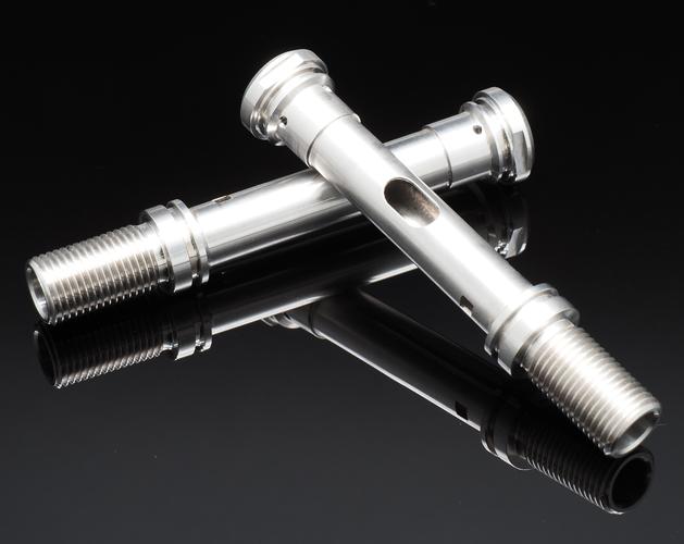
Shafts, bolts, bushings, bearing rings (rotational symmetry parts)
|
~40% of CNC machining
|
|
CNC Milling
|
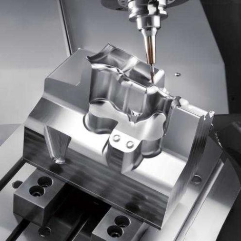
Workpiece stays fixed; tool rotates (spindle-driven) to cut complex contours.
|
Housings, brackets, gears, keyways (irregular shapes)
|
~55% of CNC machining
|
Synergistic Scenario: A “shaft with a keyway” (common in mechanical systems) requires Turning first (to shape the cylindrical body) and Milling second (to cut the rectangular keyway)—this combination covers 60% of mechanical part production (Source: 2025 Global CNC Machining Market Report).
2. Core Differences & Common Ground
To choose the right process or combine them effectively, understanding their key distinctions is critical.
A. Key Differences (Table Comparison)
|
Aspect
|
CNC Turning
|
CNC Milling
|
|
Motion Logic
|
Workpiece rotates (C-axis), tool moves linearly (X/Z-axis).
|
Tool rotates (spindle), tool moves in 3-5 axes (X/Y/Z/A/B).
|
|
Tool Type
|
Single-point tools (e.g., external turning tools, boring bars).
|
Multi-point tools (e.g., end mills, face mills, ball mills).
|
|
Material Removal
|
Continuous cutting (high efficiency for cylindrical parts).
|
Intermittent cutting (handles hard materials better).
|
|
Precision Range
|
±0.001-0.005mm (ideal for rotational symmetry).
|
±0.002-0.01mm (superior for complex 3D shapes).
|
|
Program Complexity
|
Simplified (focus on linear/cycle codes like G71).
|
Higher (needs arc/3D interpolation like G02/G03).
|
B. Common Ground (Shared Technologies)
- Program Structure: Both follow “Header → Preparatory Codes → Execution Codes → End” (e.g., O0001 for header, M30 for end).
- Safety Instructions: Shared core codes like M03 (spindle forward), M08 (coolant on), and G54 (workpiece coordinate system).
- Quality Control: Rely on tool offsets (G41/G42 for milling, Txxyy for turning) and real-time monitoring to reduce defects.
3. Critical Technologies for Synergistic Processing
When combining Turning and Milling (e.g., for a “stepped shaft with a cross hole”), mastering these technologies ensures efficiency and accuracy:
A. Process Sequencing Principle
Follow “Rough to Fine, Turning first then Milling”:
- Rough Turning: Remove 80-90% of excess material from the workpiece (faster than rough milling for cylindrical shapes).
- Finish Turning: Achieve final cylindrical dimensions (e.g., φ20±0.003mm) to avoid milling-induced deformation.
- Milling: Cut non-rotational features (e.g., keyways, holes) — mill after turning to use the finished cylindrical surface as a reference for alignment.
Case: A automotive parts factory reversed the order (milled first, then turned) and saw a 30% increase in keyway position deviation (from ±0.1mm to ±0.13mm) (Source: CNC Process Optimization Case Study 2025).
B. Coordinate System Alignment
The biggest challenge in synergistic processing is ensuring consistent workpiece zero point between turning and milling:
- Use a common datum (e.g., the right end face of the shaft):
-
- After turning, mark the datum with a dial indicator (error <0.002mm).
-
- When clamping for milling, align the datum to the milling machine’s G54 coordinate system (use edge finders or touch probes).
- For complex parts, use CNC Turn-Mill Centers (integrated turning and milling in one machine) — this eliminates re-clamping errors, reducing alignment time by 60% (Source: Machinery Automation Report).
C. Key Codes for Synergy
|
Scenario
|
Turning Codes (FANUC)
|
Milling Codes (FANUC)
|
|
Set workpiece coordinate
|
G50 / G54
|
G54 / G55
|
|
Rough material removal
|
G71 (rough turning cycle)
|
G73 (peck milling cycle)
|
|
Complex contour cutting
|
G70 (finish turning)
|
G02/G03 (arc interpolation)
|
|
Tool radius compensation
|
— (single-point tool)
|
G41 (left compensation) / G42 (right compensation)
|
4. Practical Workflow: Machining a “Shaft with Keyway”
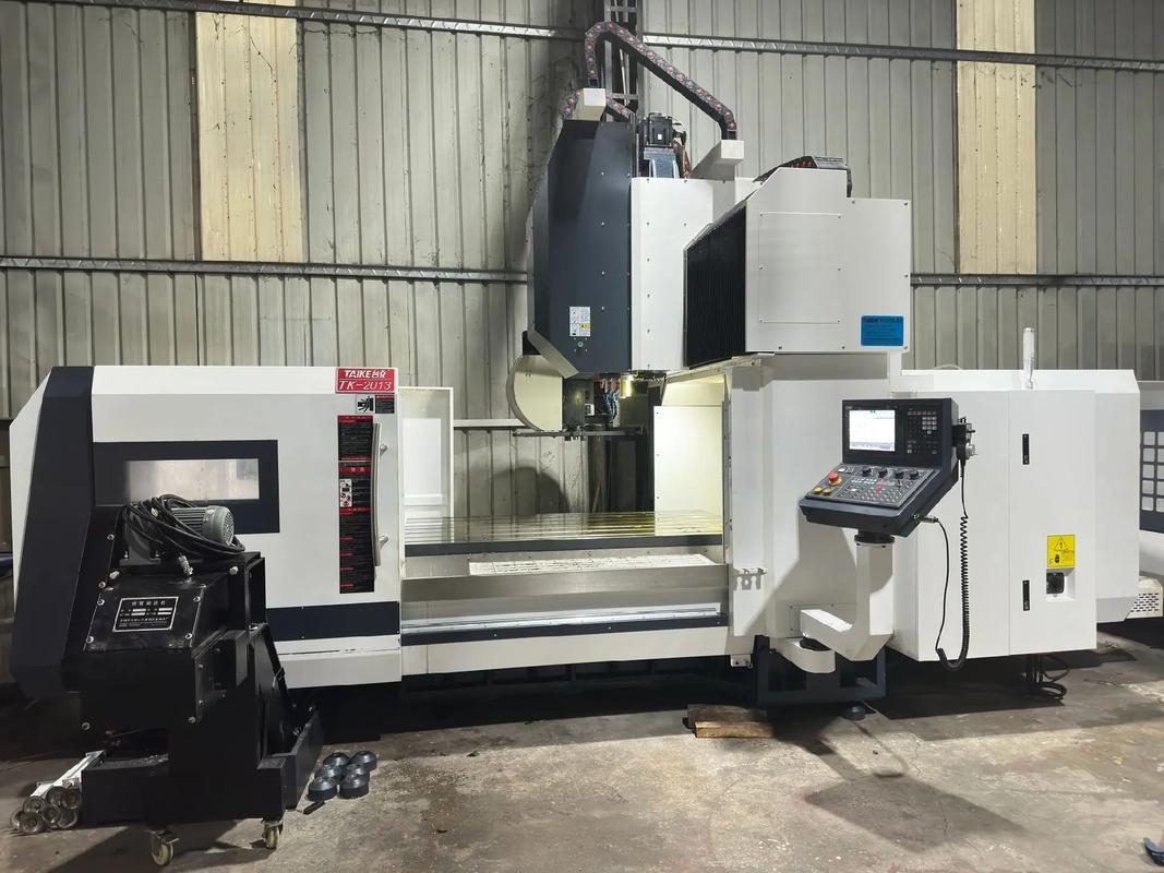
Part Specs: φ25×80mm shaft, 6×6mm keyway (depth 3mm, length 20mm) — using a FANUC 0i-TF turning center + FANUC 0i-MF milling machine.
Step 1: Drawing & Process Analysis
- Turning Requirements: φ25 (IT6 tolerance: φ24.984-25), chamfer C1, length 80mm.
- Milling Requirements: 6×6mm keyway (symmetric to shaft center, position tolerance ±0.05mm).
Step 2: Equipment & Tool Selection
|
Process
|
Machine
|
Tool
|
Parameters
|
|
Rough Turning
|
FANUC 0i-TF
|
T0101 (external turning tool)
|
S1800r/min, F0.25mm/rev
|
|
Finish Turning
|
FANUC 0i-TF
|
T0101
|
S2200r/min, F0.1mm/rev
|
|
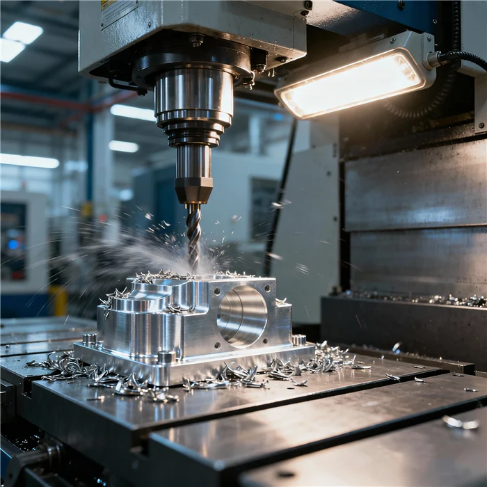
Milling Keyway
|
FANUC 0i-MF (3-axis)
|
Φ6mm end mill (T0303)
|
S3000r/min, F150mm/min
|
Step 3: Collaborative Programming (Key Snippets)
A. Turning Program (O0001)
O0001 (Shaft Turning Program)
G99 G54 S2200 (Set feed unit: mm/rev; G54 coordinate; max spindle speed)
T0101 M03 S1800 (Rough turning tool; spindle forward)
M08 (Coolant on)
G00 X30 Z2 (Rapid to safe position)
G71 U2 R1 (Rough cycle: depth 2mm, retract 1mm)
G71 P10 Q20 U0.2 W0.1 F0.25 (Finish allowance: X0.2, Z0.1)
N10 G00 X23 Z0 (Finish contour start)
G01 X25 Z-1 F0.1 (Chamfer C1)
Z-80 (Turn to length 80mm)
N20 G00 X30 Z2 (Finish contour end)
G70 P10 Q20 (Finish turning)
G00 X100 Z100 (Return to origin)
M05 M09 (Spindle stop; coolant off)
M30 (Program end)
B. Milling Program (O0002)
O0002 (Keyway Milling Program)
G90 G54 G00 X0 Y0 Z10 (G54 coordinate; rapid to above workpiece)
S3000 M03 (End mill spindle forward)
M08 (Coolant on)
G43 Z5 H03 (Tool length compensation)
G01 Z-3 F150 (Cut to keyway depth 3mm)
G01 X20 F150 (Mill keyway length 20mm)
G00 Z10 (Retract tool)
X0 Y0 (Return to start)
M05 M09 (Spindle stop; coolant off)
M30 (Program end)
Step 4: Simulation & Trial Cutting
- Turning Simulation: Verify no tool collision with chuck (G00 X30 Z2 is safe).
- Milling Alignment: Use a dial indicator to align the shaft’s φ25 surface to G54 X0 (error <0.003mm).
- Trial Cutting: Use scrap material to test keyway depth (adjust Z-axis offset if 6mm keyway is too shallow/deep).
5. Common Problems & Solutions (Synergistic Scenarios)
1. Keyway Position Deviation (Milling After Turning)
- Cause: Workpiece re-clamping shifts the datum (e.g., shaft rolls in milling vice).
- Solution: Use a V-block fixture (matches shaft curvature) for milling, or mark a reference line during turning to align with milling machine.
2. Tool Interference (Milling Complex Shafts)
- Cause: End mill hits the shaft’s stepped surface (e.g., milling a keyway near a shoulder).
- Solution: Add a “safe retract” code (G00 Z5) before moving the tool across steps, or use CAM software (e.g., Mastercam) to simulate the tool path.
3. Dimensional Instability (Turning Then Milling)
- Cause: Milling vibrations deform the thin shaft (e.g., φ10×100mm shaft bends during keyway cutting).
- Solution: Reduce milling feed rate (from 200mm/min to 100mm/min) or use a supporting center (reduces deflection by 40%).
6. Q&A: High-Frequency Questions for Synergistic Processing
Q1: Should I choose a Turn-Mill Center or separate machines?
- Small-batch (≤50 parts): Separate machines (lower upfront cost: ~(80k vs. )200k for turn-mill centers).
- Mass production (>100 parts): Turn-Mill Centers (eliminates re-clamping, reduces cycle time by 35% — Source: CNC Equipment Cost-Benefit Report).
Q2: How to calculate cutting parameters for both processes?
- Turning: Spindle speed S = (1000×Vc) / (π×D) (Vc=150m/min for aluminum, D=shaft diameter).
- Milling: Feed rate F = S×Z×fz (Z=number of end mill flutes, fz=0.1mm/flute for aluminum).
Q3: Can I use the same G-code for different systems (e.g., SIEMENS vs. FANUC)?
- Core logic is consistent, but code formats differ:
-
- FANUC rough turning: G71 U2 R1 → SIEMENS: CYCLE95(“ROUGH”, 2, 1, …).
-
- Always refer to the machine’s manual or use a “cross-system code converter” (e.g., CAMWorks).
Final Thought
CNC Turning and Milling are not competing processes—their synergy unlocks the production of 70% of mechanical parts (from simple shafts to complex engine components). The key to success lies in reasonable process sequencing, accurate coordinate alignment, and proactive error prevention.
Have you encountered challenges in combining turning and milling (e.g., datum alignment, tool selection)? Or do you need a program for a specific part (e.g., a shaft with multiple keyways)? Share your needs in the comments—I’ll provide targeted guidance!